|
Das Kreditwerk in Bergmann-Musikboxen ist etwas
kompliziert zu durchschauen. Das Kreditwerk selbst besteht aus einem
Motor, der einen Hebel dreht. Dieser Hebel nimmt ein Zahnrad eine
bestimmte Anzahl von Schritten mit. Die Stellung dieses Zahnrads
repräsentiert die Anzahl der verfügbaren Kredite - max. 36. Es wird bei
jeder Wahl um einen Schritt zurückgestellt, bis es in die
Ausgangsstellung zurück ist und einen Kontakt öffnet, wodurch die
Wahlbereitschaft beendet wird.
Die Münzkontakte sind anders als üblich konstruiert. Wenn ein
Münzkontakt betätigt wird, während der Löschmagnet angezogen ist, rastet er ein und bleibt
geschlossen, bis der Löschmagnet abfällt. Der Münzkontakt schaltet den
Kreditmotor entweder allein ein (wenn der Münzkontakt für die höchste
Kreditanzahl gedrückt ist) oder zusammen mit einer Stoppspule auf dem
Kreditwerk. Die Stoppspulen begrenzen den Weg, den der Hebel
zurücklegen kann. Für die Münze mit der höchsten Wertigkeit gibt es noch
einen unbeweglichen Anschlag. Spulen und Anschlag können entsprechend
der gewünschten Kreditanzahl versetzt werden.
Der Löschmagnet wird über einen Brückengleichrichter und einen 50 Ohm -
Widerstand versorgt. Er ist also dauerhaft angezogen.
Damit er abfallen und damit den Münzkontakt zurückstellen kann, müssen die
AC Anschlüsse des Brückengleichrichters kurzgeschlossen
werden. Genau das macht der Hebel, wenn er gegen den fixen Anschlag bzw.
gegen einen der Spulenplunger der Stoppspulen (falls eine aktiviert ist) fährt.
Der Löschmagnet fällt ab und der Münzkontakt wird freigegeben. Dadurch
wird der Motor abgeschaltet und der Hebel kehrt in die Ausgangsstellung
zurück. Dadurch wird der Kurzschluss des Löschmagneten aufgehoben und
dieser zieht wieder an.
Wenn das Kreditwerk die maximal mögliche Kreditanzahl aufgezogen hat,
wird ein weiterer Kontakt betätigt, der ebenfalls den Gleichrichter für
den Löschmagneten kurzschließt. Dieser fällt ab und verhindert dadurch,
dass weitere Münzen angenommen werden.
Zu erwähnen ist noch, dass die Masse des Kreditwerks nicht identisch ist
mit dem "0" - Anschluss des Trafos.
|
|
The credit unit in Bergmann
jukeboxes is slightly complicated and not as easy to understand. The
credit unit itself consists of a motor which turns a lever. This lever
activates a certain amount of stepson a gearwheel. The position of this
gearwheel represnets the amount of credits available - max. 36. With
each selection it gets reset for one step until it reaches its starting
position opening a contact which ends the possibility for selections.
The coin contacts are
constructed different than usually. When a coin contact gets activated
while the lock bar solenoid is energized, it engages and remains closed
until the locking coil de-energizes. The coin contact activates the
motor either by itself (if the coin contact is activated for the
highest amount of credits) or together with a stop coil on the
credit unit. The stop coils limit the distance the lever can travel.
There is also a fixed stop for the coin contact with the highest
denomination. Solenoids and stopping can be moved according to the desired
number of credits.
The cancel solenoid get
supplied via a bridge rectifier and a 50 Ohm resistor. It is attracted
permanently.
So that the cancel solenoid gets de-energized and thus reset the coin
contact, the AC voltage connections of the bridge rectifier must be
short-circuited. This is exactly what the lever does when it moves
against the fixed stop or one of the coil plungers of the stop coils (if
one is activated). The cancel solenois de-energizes and the coin contact
is released. This switches off the motor and the lever returns to its
initial position. This overrides the short circuit of the cancel
solenoid and it attracts again.
When the credit unit has established the maximum possible number of
credits, another contact is actuated which also short-circuits the
rectifier for the cancel solenoid. This de-energizes out and thus
prevents further coins from being accepted.
It should also be mentioned that the ground of the credit unit is not
identical to the "0" connection of the transformer. |
|
Information und Fotos:
karotiger
|
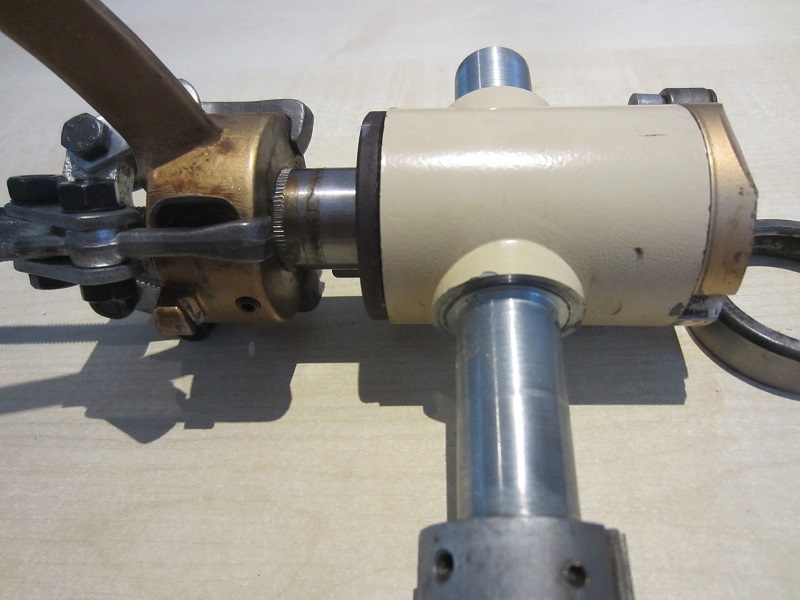
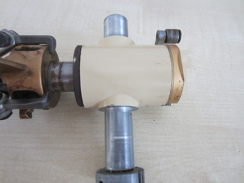
Der eigentliche Greifarm ist auf
seiner Achse aufgepresst und lässt sich nach Demontage des Druckstückes
(das Teil, welches die Platte klemmt) und der darunter liegenden
Bundmutter mittels Abzieher entfernen. Dazwischen befinden sich jeweils
noch eine Feder.
|
|
The actual
gripper arm is pressed onto its shaft and can be removed after
dismantling the pressure piece (the part that clamps the record)
and the collar nut underneath by using a puller.
There is a spring each between them. |
|
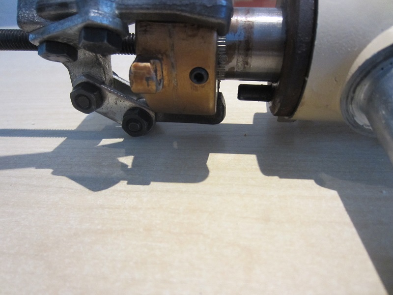
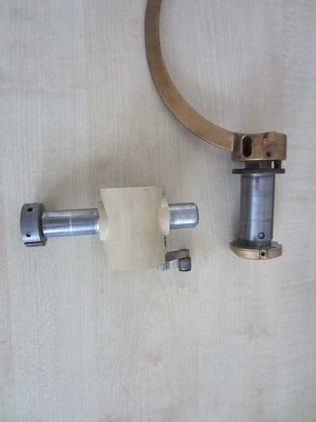
Jetzt habe ich den Mechanismus im Inneren geöffnet und verstanden. Dort
befinden sich zwei Schiebestücke und ein Zahnrad, welches beide
verbindet.
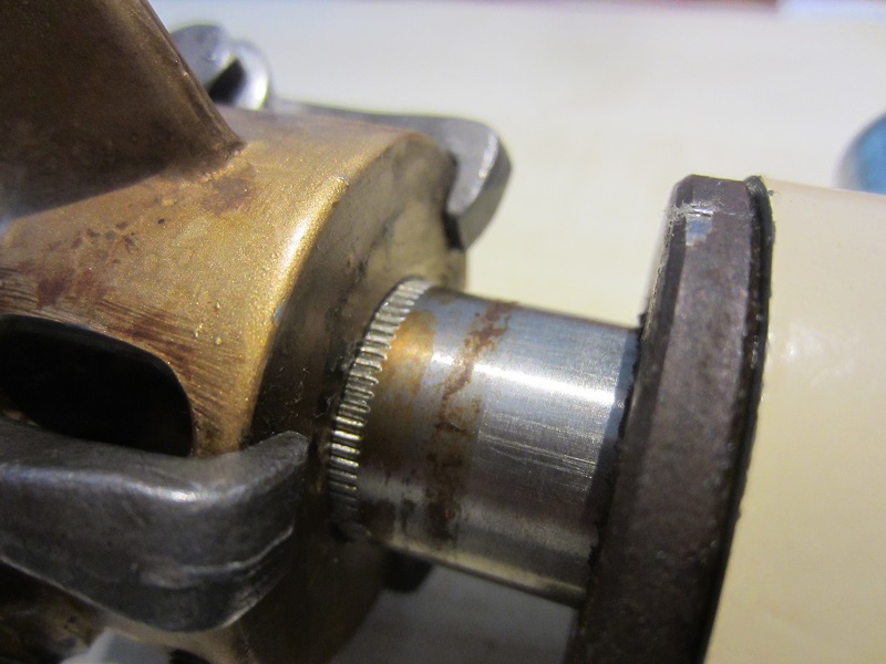
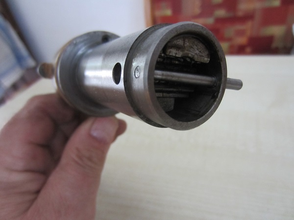
Mit Abnehmen des hinteren goldenen Deckels kann man die Greifereinheit
noch vorne herausziehen. Dazu muss ein Querstift aus dem hinteren Deckel
herausgeschlagen werden (siehe Bilder). Beim Herausziehen fällt dann die
Welle des Verbindungszahnrades heraus - bei der Montage muss der wieder
in die richtige Position.
Nun ist das Geheimnis gelüftet und die Büchse auf....und echt gut
gemacht, wenn man es sich anschaut. |
|
Now I have
opened and understood the mechanism inside. There are two
sliding pieces and one gear wheel that connects the two parts.
By removing the rear gold cover, you can pull out the gripper
assembly from the front. To do this, a cross pin must be knocked
out of the rear cover (see pictures). When you pull it out, the
shaft of the connecting gear falls out - it must be put back
into the correct position when you reassemble it.
Now the secret is not hidden any longer and "Pandorra's box"
open....and really well done, if you look at it. |

|
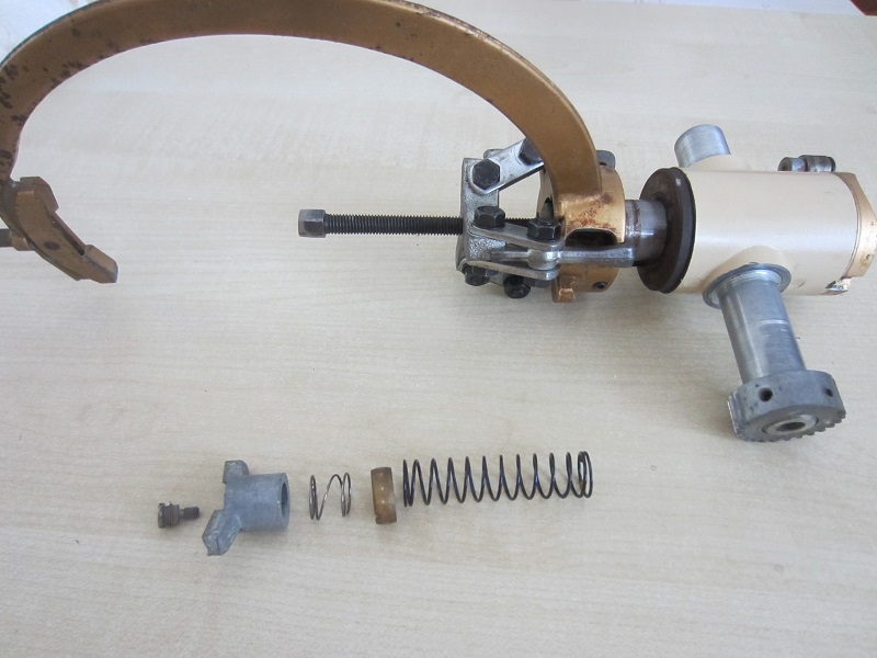
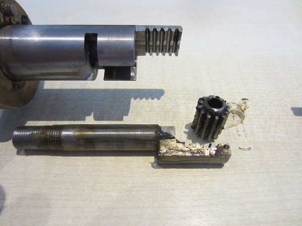
Ich habe noch einmal den
Klemmmechanismus kpl. zerlegt - so sollte die Funktion klar
sein. |
|
I have
disassembled the clamping mechanism once again - so the function
should be obvious. |
 |