|
Werden diese Arbeiten das erste Mal gemacht,
ist es sinnvoll, die einzelnen Schritte mittels Fotos
zu dokumentieren.
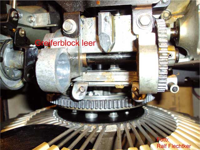
Wenn die Greifermechanik komplett feststeckte, sollte sie auf jeden
Fall zerlegt, gereinigt und geschmiert werden.
Hinweis:
Die Greifermechanik darf niemals demontiert
werden wenn sich der Korb auf der freien Stelle (Parkposition oder "0"
Stellung) befindet. Hintergrund ist dass die Mechanik für A-B Seiten
Umlenkung dann in keiner definierten Position ist, also weder die A-
noch die B-Seite richtig umgelenkt wird. So kann das dafür
verantwortliche Gussteil beschädigt oder zerstört werden.
Zerlegung
-
eine Platte auflegen lassen und den
Serviceschalter auf OFF stellen
-
die aufgelegte Platte und den
Plattenteller herausnehmen
-
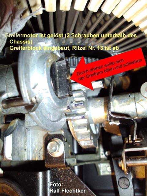
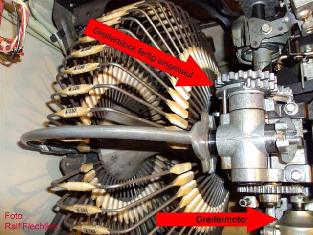
Greifermotor abschrauben und soweit
lockern, dass sich das große Zahnrad mit der Hand drehen lässt. Das
Zahnrad soweit zurückdrehen, dass der Greifer schließt, aber noch
neben dem Plattenteller liegt.
-
die zwei Zahnräder auf der Hinterseite
des Greifergelenks abnehmen.
-
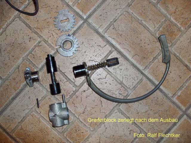
nun das Klemmstück, das die Platte
festklemmen soll, in Richtung Plattenmagazin drücken. Dadurch kommt
auf der anderen Seite des Gelenks das Umlenkstück heraus. Dieses ist
mit einem Spannstift befestigt. Diesen Spannstift mit Hilfe eines
Splinttreibers heraus treiben. Dabei darauf achten, dass der Stift
nicht in das Greifergehäuse fällt (mit einer Spitzzange festhalten).
-
das Umlenkstück abziehen und auch den
Greiferbügel (mit dem Klemmstück und der Feder dazwischen) heraus
nehmen.
-
den Bolzen herausziehen und auch das
Gelenkstück herausnehmen
|
|
If this work is
being carried out for the first time, it is advisable to
document the individual steps using photos. If the gripper
mechanism was completely stuck, it should always be disassembled,
cleaned and relubricated.
Note:
The gripper assembly must never be dismantled when the magazine
is in the free position (park position or "0" position). The
reason for this is that the mechanism for A-B side changeover is
then not in a defined position, i.e. neither the A nor the B
side gets properly switched over. This can damage or even
destroy the casting that is responsible for this.
Dis-assmbling
- Place a
record on the turntable and set the service switch to OFF
- Remove the
inserted record and the turntable
- Unscrew the
gripper motor and loosen it until the large gear wheel can
be turned by hand. Turn the gear wheel back until the
gripper closes but is still next to the turntable.
- Remove the
two gear wheels on the rear side of the gripper joint.
- Now push the
clamping piece, which is supposed to clamp the record, in
the direction of the record magazine. This causes the
reversing cam to come out on the other side of the joint.
This is fastened with a roll pin. Drive out this roll pin
with the aid of a pin driver.
Make sure that the pin does not fall into the gripper
housing (hold with needle-nose pliers).
- Pull off the
deflection piece and also remove the hook bracket (with the
clamping piece and the spring in between).
- Pull out the
pin and also remove the joint piece
|
Zusammenbau
Nach sorgfältiger Reinigung
müssen die Teile ohne zu klemmen zusammenpassen. Wenn es irgendwo eine
schwergängige Stelle gibt (z. B. durch eine angerostete Oberfläche), ist das vor
dem Zusammenbau zu beheben. Dann wird alles leicht geölt (am
besten mit Ballistol) und in umgekehrter Reihenfolge wieder
zusammengebaut.
Beim Einschlagen des Spannstiftes ist darauf zu achten, dass er nicht zu
weit eingeschlagen wird und ggfs. auf der anderen Seite
herausragt. Wenn alles zusammengebaut ist, dreht man mehrmals am Zahnrad
von einer Endstellung zur anderen. Der Greifer muss sich leicht (ohne
zu klemmen und ohne schwergängige Stellen) bewegen, öffnen und
schließen.
Im Detail -
dank an charly49:
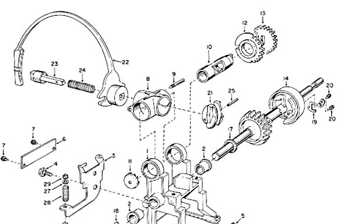
Nach der Reinigung werden die Teile in der Reihenfolge 8 - 10 - 22 - 24
- 23 - 21 zusammengesteckt. Der Greifer sollte dabei in der gleichen
Position wie vor dem Zerlegen (neben dem Plattenteller) liegen. Dann
kann man den Spannstift (25) einsetzen. Der Spannstift muss schön bündig
sein, damit das Umlenkstück (21) ohne zu klemmen in das Gelenkstück (8)
rutschen kann. Jetzt müsste sich der Greifer ganz leicht von Hand zum
Magazin und zurück bewegen lassen. Wenn man den Greifer in einer
Mittelstellung festhält und den Ansatz auf der Welle, auf den das
hintere Zahnrad kommt, mit einer Zange um etwa 30° nach links oder
rechts verdreht, müsste sich der Greifer öffnen. Beim Loslassen müsste
sich die Welle durch die Federkraft zurückdrehen und der Greifer müsste
wieder schließen.
Der schwierigste Teil ist das Aufstecken des ersten Zahnrads (12). Es
lässt sich nur aufstecken, wenn man den Greifer in eine Mittelstellung
(etwa senkrecht hoch) stellt. Wie man sieht, fehlen sowohl bei diesem
Zahnrad als auch bei seinem Gegenstück einige Zähne. Die vorhandenen
Zähne müssen genau zusammenpassen, das ist nur in einer einzigen
Position der Fall. Wenn alles richtig ist, sollte sich nun der Greifer
durch Drehen am großen Zahnrad (auf das der Motor eingreift) zum Magazin
und zurück bewegen lassen. Zudem muss sich des Zahnrad in beiden
Richtungen noch um etwa 30° weiter drehen lassen, wenn der Greifer schon
in der Endstellung ist. Wenn es sich in eine Richtung nicht weiter
drehen lässt, stimmt die Position von Zahnrad 12 noch nicht. Es kann
sein, dass man einige Male probieren muss, bis es passt. Man kann jetzt
auch schon die Mikroschalter auf richtigen Schaltpunkt überprüfen.
Ansonsten wird es gemacht, wenn alles zusammengebaut ist.
Wenn alles so weit in Ordnung ist, kann man das letzte Zahnrad
aufstecken. Dazu stellt man den Greifer wieder etwa in senkrechte
Stellung und steckt das Zahnrad auf, ohne die Welle zu verdrehen. Der
Zapfen (9) auf dem Gelenkstück sollte genau mittig auf dem zahnlosen
Teil des Zahnrads stehen. Dann kann man das Zahnrad anschrauben und
einige Male durch Drehen des großen Zahnrads mit der Hand die korrekte
Funktion (reibungslose Bewegung des Greifers, Öffnen und Schließen)
überprüfen.
|
|
Assembly
After careful cleaning, the parts must fit together without
jamming. If there is a stiff spot somewhere (e.g. due to a rusty
surface), this must be rectified before re-assembling.
Then lightly
oil everything (preferably with Ballistol) and re-assemble in
reverse order.
When driving in the roll pin, make sure that it is not driven
in too far and possibly protrudes on the other side. When
everything is assembled, turn the gear wheel several times from
one end position to the other. The gripper should move, open and
close easily (without jamming and without stiff spots).
In detail -
thanks to charly49:
After
cleaning, the parts are arresmbled together in the sequence 8 -
10 - 22 - 24 - 23 - 21. The gripper should be in the same
position as it was before dis-assembling (next to the turntable).
Then the roll pin (25) can be inserted. The roll pin must be
flush mounted so that the reversing cam (21) can slide into the
joint (8) without jamming. It should now be easy to move the
gripper to the magazine and back by hand.
If you hold the gripper in a central position and use pliers to
turn the shoulder on the shaft on which the rear gear wheel is
mounted by about 30° to the left or right, the gripper should
open. When released, the shaft should turn back due to the
spring force and the gripper should close again.
The most difficult part is fitting the first gear wheel (12). It
can only be fitted if the gripper is set to a central position (approximately
vertically upwards). As you can see, both this gearwheel and its
counterpart are missing some teeth. The existing teeth must fit
together exactly, which is only the case in one position. If
everything is correct, it should now be possible to move the
gripper to the magazine and back by turning the large gear wheel
(on which the motor engages). It should also be possible to turn
the gear wheel by about 30° in both directions when the gripper
is already in the end position.
If it cannot be turned any further in one direction, the
position of gear 12 is not yet correct. You may have to try a
few times until it fits.
You can now also check the microswitches for the correct
switching point. Otherwise it will be done when everything is
assembled.
Once everything is in order, the last gear can be fitted. To do
this, return the gripper to a roughly vertical position and fit
the gear wheel without turning the shaft. The pin (9) on the
joint should be exactly centered on the toothless part of the
gearwheel. You can then screw on the gear wheel and check the
correct function (smooth movement of the hook, opening and
closing) by turning the large gear wheel a few times by hand.
|