|
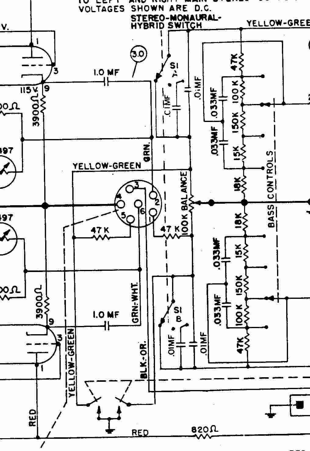
Um im Hybrid-Betrieb Stereo an den Außenlautsprechern und gleichzeitig rückwirkungsfrei Mono an den Gerätelautsprechern wiederzugeben, wird für die Gerätelautsprecher der rechte und der linke Kanal sozusagen summiert. Die Eigenheit des Tempo-II-Verstärkers besteht nun darin, dass für diese Summenbildung das Signal eines Kanals invertiert vorliegen muss (deswegen muss bei der Tempo II ein Kanal am Tonsystem phasenvertauscht angeschlossen sein; dies ist nur bei Tempo II so, ab der Regis wurde das geändert!). Das heißt aber, dass ein phasengleich in beiden Kanälen vorliegendes Signal sich an den Gerätelautsprechern schaltungsbedingt aufhebt, jedoch in den Außenlautsprechern hörbar bleibt (wenn es auch wegen der Phasenlage der Außenlautsprecher etwas "seltsam" klingen kann). Zum Schaltplan des
Verstärkers (aus dem Gesamtschaltbild):
Die Gerätelautsprecher
werden über S1C und S1D geschaltet, bei Stereo sind sie abgeschaltet,
bei Mono und Hybrid in Betrieb. Nicht ganz logisch, das mit der
"Mono"-Position, aber ab der Regis wurde dies verbessert. aus Gesamtschaltplan 1485 117V: |
In order to reproduce stereo at the external speakers and simultaneously mono at the cabinet speakers without feedback in hybrid mode, the right and left channels are, so to speak, summed for the cabinet speakers. The specail nature of the Tempo II amplifier is that the signal of one channel must be inverted for this summation (this is why one channel of the Tempo II must be connected to the cartridge phase inverted; this is only the case with Tempo II, this has been changed from the Regis onwards). This means, however, that an in-phase signal in both channels cancels itself out at the cabinet speakers due to the circuitry, but remains audible in the external speakers (even if it can sound somewhat “strange” due to the phase position of the external loudspeakers). To the circuit diagram
of the amplifier (from the overall circuit diagram):
The cabinet speakers are
switched via S1C and S1D, in stereo they are switched off, in mono
and hybrid they are in operation. The “mono” position is not
entirely logical, but this has been improved from the Regis onwards.
From schematic wiring diagram 1485 117V: |
|
|
|
||
|
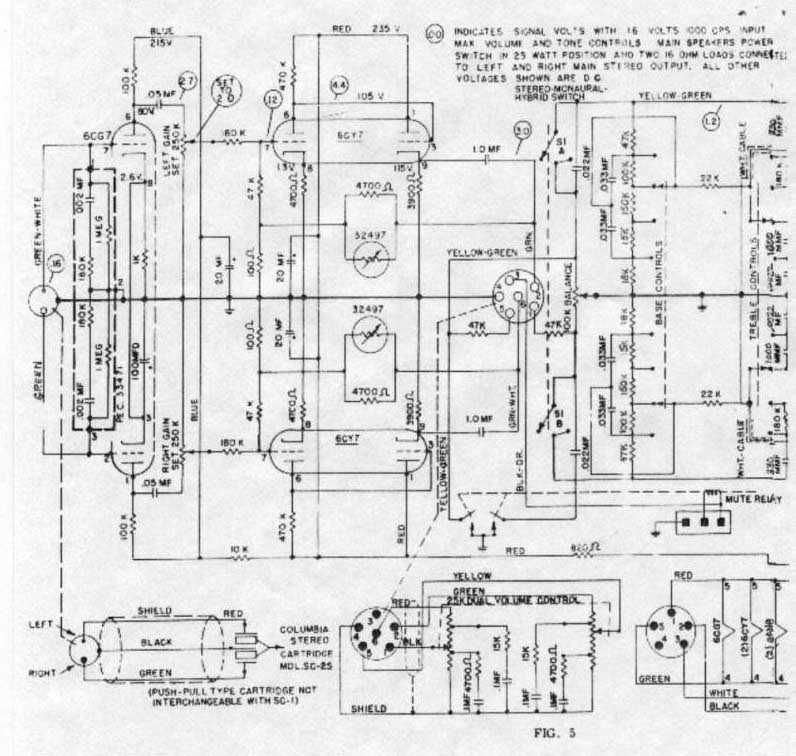
Andere Version des
Schaltplanes (aus Gesamtschaltplan 1478 - 117V): |
Different version of
schematic (schematic wiring diagram 1478 - 117V): |
|
|
|
||
Sobald das "Play Control
Relays" anzieht, gibt es ein Brummen in den Zusatzlautsprechern.
Ich hab den Plattentellermotor und den Korbmotor ausgesteckt, ebenso
Beleuchtung. Erfolglos. Sobald ich den Serviceschalter auf SCAN stelle,
oder auf OPERATE und eine Wahl tätige, brummt es. Aber nur in den
Zusatzlautsprechern, nicht in den Lautsprechern der Musikboox.
Es ist mir aufgefallen das dabei die vier Rohren 6973 kurz blau
aufleuchten.
Antwort:
Verändert sich der Brumm mit dem Betätigen des Lautstärkereglers?
Verändert sich der Brumm, wenn der Muting-Stecker (3-poliger
Plastikstecker) gezogen wird?
Verändert sich der Brumm, wenn der Input-Stecker gezogen wird?
Werden alle drei Fragen mit "Nein" beantwortet, vermute ich, daß
der Brumm aus der Anodenspannungsversorgung kommt.
Und dass der Brumm bei den (Mono-)Gerätelautsprechern nicht zutage tritt,
würde sich mit der Eigenheit des Tempo-II-Verstärkers erklären:
Um im Hybrid-Betrieb Stereo an den Außenlautsprechern und gleichzeitig
rückwirkungsfrei Mono an den Gerätelautsprechern wiederzugeben, wird für
die Gerätelautsprecher der rechte und der linke Kanal sozusagen
summiert. Die Eigenheit des Tempo-II-Verstärkers besteht nun darin, daß
für diese Summenbildung das Signal eines Kanals invertiert vorliegen muß
(deswegen muß bei der Tempo II ein Kanal am Tonsystem phasenvertauscht
angeschlossen sein; dies ist nur bei Tempo II so, ab der Regis wurde das
geändert !). Das heißt aber, daß ein phasengleich in beiden Kanälen
vorliegendes Signal sich an den Gerätelautsprechern schaltungsbedingt
aufhebt, jedoch in den Außenlautsprechern hörbar bleibt (wenn es auch
wegen der Phasenlage der Außenlautsprecher etwas "seltsam" klingen
kann).
Zum blauen Leuchten: das
ist durchaus normal, wenn es ein schönes Blau ist. Es ist im Inneren des
Anodenbleches zu sehen (manchmal leuchtet auch das Glas innen leicht
blau) und verändert sich mit der Musik.
Schlecht wäre ein hellrosa-hellviolettes Leuchten, und auch ein Glühen
der Anode oder des Schirmgitters. Glühen darf nur der Heizfaden und die
Kathode.
As soon as the “Play Control
Relays” is attracted, there is a humming noise in the auxiliary speakers.
I did unplug the turntable motor and the magazine motor, as well as the
lighting. There was no success. As soon as I set the service switch to
SCAN, or to OPERATE and make a selection, there is a hum. But only in
the auxiliary speakers, not in the loudspeakers of the jukebox itself.
I have noticed that the four 6973 valves light up blue briefly.
Answer:
Does the hum change when the volume control is operated?
Does the hum change when the muting plug (3-pin plastic plug) is pulled
out?
Does the hum change when the input plug is pulled out?
If all three questions are answered with “no”, I suspect that the hum
comes from the anode voltage supply.
And the fact that the hum does not occur with the (mono) cabinet
speakers would be explained by the particuliar characteristic of the
Tempo II amplifier:
In order to reproduce stereo on the external speakers and simultaneously
mono on the cabinet speakers without feedback in hybrid mode, the right
and left channels areso to speak, summed, for the cabinet speakers. The
particularity
of the Tempo II amplifier is that the signal of
one channel must be inverted for this summation (this is why one channel
of the Tempo II must be connected phase inverted to the cartridge; this
is only the case with Tempo II, this has been changed from the Regis
onwards). This means, however, that an in-phase signal in both channels
cancels itself out at the cabinet speakers due to the circuitry, but
remains audible in the external loudspeakers (even if it can sound
somewhat “strange” due to the phase position of the external speakers).
Regarding the blue glow: This
is quite normal if it is a nice blue. It can be seen inside the anode
plate (sometimes the glass inside also glows slightly blue) and changes
with the music.
A light pinkish-pale violet glow would be bad, as would a glowing anode
or screen grid. Only the filament and the cathode should glow.
Das originale TA-System der
Tempo 2/120 oder Tempo 2/200 war das "Columbia SC-2S".
Die besondere Eigenschaft dieses Systems war eine Phasendrehung zwischen
dem rechtem und linken Kanal.
Genau wegen dieser Systemeigenschaften wurde der Tempo 2-Verstärker vom
Konstrukteur ebenfalls mit einer Phasendrehung konzipiert, was die
Systemeigenschaften des "Columbia SC-2S" wieder ausglich - siehe
Besonderheit.
Benutzt man heute ein "normales" Stereo-System, das eben keine
Phasendrehung beinhaltet, führt die Phasendrehung im Verstärker dazu,
dass die Box "flau" klingt und kaum Bässe bringt, denn gerade die tiefen
Frequenzen löschen sich aus, heben sich gegenseitig auf.
Da ein originales Columbia-System heute kaum zu bekommen sein wird, muss
man bei einem "normalen" Ersatz-Tonabnehmer-System einen Kanal
phasengedreht anschließen, um eben diesen Auslöschungeffekt
zu vermeiden.
Dazu muss das "normale" System aber 4 Anschlüsse, also
2 x Masse (Ground oder "G") und je einmal
"L" für linker Kanal und
"R" für rechter Kanal haben.
Man sieht das
ELAC-System sehr häufig in Tempo 2, Regis und Empress und
sogar in Mono-Tempo 1-Modellen. Aber für Tempo 1 in mono (sie hatte ab
Werk ein Magnetsystem) und für Tempo 2 ist das ELAC KST 103
eher ungeeignet.
Grund: ELAC-Stereo-Systeme haben eine gemeinsam aus dem System
herausgeführte Masse, so dass ein phasengedrehter Anschluss eines der
beiden Kanäle gar nicht möglich ist.
Es empfiehlt sich also, ein anderes Stereosystem in Tempo 2 zu
verwenden.
Im Schaltplan vom NOVA
Verstärker für die Tempo 2 steht dieser Hinweis:
Stereo Cartridge Columbia SC-2S oder ELAC KST
105
NOT SC-1 or KST 103.
Damit dürfte klar sein, dass das Elac KST 103 original nicht für die Tempo 2
verwendet wurde.
Vermutlich wurden im Laufe der Zeit defekte Systeme aus Unwissenheit
durch den Typ KST 103 ersetzt.
► Anmerkung Stamann: es gab das KST 105. Optisch
sieht es wie das KST 103 aus, hat aber die Bezeichnung mit "105".
Außer dem Push-Pull TA-Eingang und der Ultralinearschaltung hat der NOVA
Verstärker mit dem originalen (USA) Verstärker nicht viel gemeinsam.
Der technische Hintergrund, wieso bei der Tempo 2 ein Gegentakt
(Push-Pull) Tonabnehmer verwendet werden muss, ist folgender:
Beim Tempo 2 Verstärker sind beide Kanäle komplett identisch aufgebaut,
das heißt auch die Ausgangsübertrager sind bei beiden Kanälen gleich
angeschlossen. Das bedeutet, dass die Phasenlage in beiden
Sekundärwicklungen der Übertrager die selbe ist (phasengleich). Durch
den speziellen TA, bei dem ein Kanal ein um 180° gedrehtes Signal
liefert sind auch die Ausgangssignale der beiden Ausgangsübertrager um
180° gedreht (invertiert). Das ist im Schaltplan daraus ersichtlich,
dass beim rechten Kanal + an Masse liegt und beim linken – an Masse. Das
ist deshalb wichtig, weil bei Mono Betrieb die beiden Kanäle gebrückt
werden (Bridge Mode. Die Kennzeichnung + und – der
Lautsprecheranschlüsse hat dabei nichts mit Gleichspannung zu tun,
sondern bezieht sich auf die Phasenlage.
Wenn an einen Tempo 2 Verstärker an beiden Kanälen ein phasengleiches
Eingangssignal mit gleichem Pegel angeschlossen ist und die Amplituden
an beiden Ausgängen mit dem Balance Regler auf den selben Wert
eingestellt sind, beträgt die Ausgangsspannung bei Mono Betrieb 0V und
somit ist im Lautsprecher kein Ton zu hören (Lautstärke natürlich
aufgedreht).
Aber warum hört man dann bei einer Tempo 2 mit KST 103 doch etwas?
Das liegt hauptsächlich daran, dass die Balance der beiden Kanäle nie
100%ig genau eingestellt ist und dass auch die Musiksignale einer
Schallplatte bei beiden Kanälen nicht komplett identisch sind. Am besten
funktioniert ein KST 103 in der Tempo 2 wenn der Balance Regler komplett
nach links oder rechts gedreht wird. Allerdings fehlt dann das Signal
von einem Kanal.
Verstärker Umbau:
Nach obiger Erläuterung könnte man als erstes auf die Idee kommen die
Verdrahtung der Primärseite von einem Ausgangsübertrager zu ändern.
Blauen mit braunen Draht an Pin 9 der beiden 6973 vertauschen und
voilà..... schon hat man die benötigte Phasendrehung, die für den Betrieb
mit einem KST103 benötigt wird. Soweit würde das auch funktionieren,
wäre da nicht die mehrstufige Gegenkopplung. Die Spannung hierfür
wird bei beiden Kanälen vom 16 Ohm Anschluss auf der Sekundärseite der Ausgangsübertrager abgenommen. Schaut man sich allerdings die
Phasenlagen der einzelnen Stufen an, wird man leider erkennen, dass sich
beim geänderten Kanal keine Gegenkopplung sondern eine Mitkopplung
ergibt. Somit also aus der Traum – zumindest ohne weitere Änderungen!
KST 103 ohne Verstärker Umbau:
Eine Möglichkeit die funktioniert ist, die beiden 12-Zöller der Musikbox an
den Main Stereo Klemmen anzuschließen die eigentlich für externe
niederohmige Lautsprecher gedacht sind und den Betriebswahlschalter auf
Stereo zu stellen. Bei einem Lautsprecher muss jedoch + und – vertauscht
werden. Das Hochtonhorn der US Ausführung (NOVA Tempo 2 haben keines)
kann bei dieser Lösung aber nur parallel zu einem der beiden 12"
Lautsprecher angeschlossen werden. Dadurch ändert sich jedoch die
Lastimpedanz an einem Kanal, was sich aber mit dem Schalter für die
Leistung anpassen lässt und die ungleiche Lautstärke der beiden
Lautsprecher kann man mit dem Balance Regler ausgleichen. Technisch ist
das sicher keine perfekte Lösung, aber wer unbedingt ein KST 103 bei der
Tempo 2 haben will ...!
Die einfachste Lösung ist aber eindeutig der beschriebene
phasenverkehrte Anschluss eines Kanals bei einem System bei dem beide
Kanäle unabhängige Anschlüsse für + und – haben.
Und wie ist das bei den Verstärkern von Regis,
Empress, Capri usw.?
Bei Regis und Empress sind die Ausgangsübertrager beim linken und
rechten Kanal anders angeschlossen. Dadurch ist trotz phasengleichem
Eingangssignal am Ausgang der linke und rechte Kanal um 180° gedreht
und somit funktioniert die Zusammenschaltung der beiden Kanäle im Mono
Betrieb auch wieder. Und die Gegenkopplung funktioniert, weil bei diesem
Verstärker andere Übertrager verwendet werden, bei denen jeweils die 4
Ohm Anzapfungen an Masse liegen und die Spannung für die Gegenkopplung
beim rechten Kanal am Fußpunkt der Wicklung (+ Anschluss rechter
Lautsprecher) und beim linken Kanal an der 16 Ohm Anzapfung der
Sekundärwicklung (+ Anschluss linker Lautsprecher) abgegriffen werden.
Bei den Verstärkern von Capri und Co. erfolgt bei den niederohmigen
Ausgängen keine Phasendrehung. Hier ist bei beiden Kanälen am Ausgang -
an Masse. Das liegt daran, dass es keine Mono Betriebsart gibt. Bei
diesen Boxen sind die internen Lautsprecher bereits stereomäßig
angeschlossen. Der 70V Line Mono Ausgang ist an einem Kanal mit - und
beim anderen mit + verbunden. ACHTUNG! In den Verstärker Schaltplänen
von Capri, Rhapsody (und evt. auch anderen) sind die Leitungsfarben blau
und braun der Primärseite des Ausgangsübertragers bei einem Kanal
verkehrt angegeben. Tatsächlich sind bei diesen Verstärkern beide
Übertrager gleich angeschlossen. Wenn die Übertrager laut Plan
verdrahtet wären, würde die Phasenlage der Ausgänge nicht wie angegeben
sein!
Übrigens, wer bei seiner Regis, Empress, Capri usw. Höhen vermisst hört
nicht unbedingt schlecht. Das liegt (auch wenn alle anderen
relevanten Komponenten in Ordnung sind) an der eigenwilligen
Klangregelung, die RO bei diesen Verstärkern verwendet hat. Bei der
Höhenregelung ist dabei nur eine Absenkung und keine Anhebung gegenüber
der Bezugsfrequenz von 1 KHz möglich. Selbst wenn der Höhenregler auf
Maximum steht, werden die Höhen stark gedämpft. Aber dafür wird mit dem
Höhenregler der Bereich um 1 KHz mitgeregelt, was eigentlich nicht
üblich ist. Einige der noch älteren RO Verstärker (bis Tempo 1) haben
eine Schaltung für Geräuschunterdrückung. Dabei wird
in Stufen die Höhenwiedergabe herabgesetzt. Dafür haben diese Verstärker
eine übliche Bass- und Höhenregelung mit einer Absenkung und Anhebung
gegenüber der Bezugsfrequenz. Vielleicht hat sich RO bei den Modellen ab
1961 gedacht, die Geräuschunterdrückung gleich mit der Klangregelung zu
erledigen: einfach generell weniger Höhen und gut. Und dann tun es auch
noch Platten mit schlechterer Qualität.
Ich halte das für einen technischen Rückschritt was RO bei diesen
Verstärkern gemacht hat.
Bei meinem Verstärker von der 1494 habe ich die Klangregelung so
ausgeführt, dass damit sowohl eine Anhebung und Absenkung gegenüber 1
KHz möglich ist und das hat sich klanglich auf jeden Falls gelohnt, da
die Box nur 2 Breitbandlautsprecher hat deren Schalldruck bei hohen
Frequenzen ziemlich stark abfällt. Und wenn man dann noch einen
Hochtöner (keinen Piezoheuler) an Stelle von einem der beiden
Breitbandlautsprecher einbaut hört man erst richtig was in Sachen
Höhenwiedergabe möglich ist. Diese kleine Modifikation soll natürlich
ohne zusätzliche Bohrungen an der Box erfolgen, damit alles wieder in
den Originalzustand gebracht werden kann!
Und zum Schluss noch eine Anmerkung zu den NOVA Verstärkern. Diese haben
eine sehr gute Klangregelung weil eine bewährte Standardschaltung
verwendet wird. Ich habe erst kürzlich einen NOVA Regis Verstärker
überholt und der war klanglich sehr gut (nachdem die WIMA Bonbons
ersetzt wurden). Und wer das Innenleben eines
NOVA Verstärker mal
genauer betrachtet, weiß danach was mit dem Begriff "deutsche
Gründlichkeit" gemeint ist.
The original pick-up used in
Tempo 2/120 and Tempo 2/200 was the “Columbia SC-2S”. The special
feature of this cartridge was a phase inversion between the right and
left channel.
It was precisely because of this cartridge characteristic that the Tempo
2 amplifier was also designed by the designer with such a phase
inversion, which compensated for the cartridge characteristic of the
“Columbia SC-2S” - see the special characteristic.
If you use a “normal” stereo pick-up today, which does not include phase
inversion, the phase inversion in the amplifier results in the speaker
sounding “flat” and hardly producing any bass, because the low
frequencies cancel each other out and eliminates each other.
Since an original Columbia cartridge will hardly be available these days,
a “normal” replacement pick-up must be connected with one channel
phase-inverted in order to avoid this canceling effect.
To do this, however, the “normal” pick-up must have 4 connections, i.e.
2 x ground (ground or “G”) and once each
“L” for the left channel and
“R” for the right channel.
You see the ELAC cartridge very often in Tempo 2, Regis and
Empress and even in mono Tempo 1 models. But the ELAC KST 103 is rather
unsuitable for Tempo 1 in mono (it had a magnet cartridge ex works) and
for Tempo 2.
The reason for this is that ELAC stereo cartridges have a common ground
that leads out of the cartridge, so that a phase-inverted connection of
one of the two channels is not possible.
It is therefore advisable to use a different stereo cartridge in the
Tempo 2.
The circuit diagram of the NOVA amplifier for Tempo 2 contains this
information:
Stereo Cartridge Columbia SC-2S or ELAC
KST 105
NOT SC-1 or KST 103.
This should make clear that the Elac
KST 103 was not originally used in model Tempo 2.
Presumably, defective cartridges were replaced by the KST 103 type over
the course of time out of not knowing better.
► Note Stamann: Cartridge KST 105
has been available. Optically it looks like KST103 but has a description
with "105".
Apart from the push-pull cartridge input and the ultralinear circuit,
the NOVA amplifier does not have much in common with the original (USA)
amplifier.
The technical background as to why a push-pull pickup must be used with
the Tempo 2 is as follows:
Both channels of the Tempo 2 amplifier have a completely identical
design, which means that the output transformers are also connected in
the same way for both channels. This means that the phase position in
both secondary windings of the transformers is the same (in-phase). Due
to the special cartridge, in which one channel supplies a signal rotated
by 180°, the output signals of the two output transformers are also
rotated by 180° (inverted). This can be seen in the circuit diagram from
the fact that the right channel has + to ground and the left channel has
- to ground. This is important because in mono mode the two channels are
bridged (bridge mode). The + and - marking of the loudspeaker
connections has nothing to do with DC voltage, but refers to the phase
position.
If an in-phase input signal with the same level is connected to both
channels of a Tempo 2 amplifier and the amplitudes at both outputs are
set to the same value with the balance control, the output voltage in
mono mode is 0V and therefore no sound can be heard in the loudspeaker (volume
turned up, of course).
But why do you still hear something when using KST103 in a Tempo 2?
This is mainly due to the fact that the balance of the two channels is
never 100% accurate and that the music signals of a record are not
completely identical on both channels. A KST 103 works best in Tempo 2
when the balance control is turned completely to the left or right.
However, the signal from one channel is then missing.
Amplifier conversion:
According to the above explanation, the first idea could be to change
the wiring of the primary side of an output transformer. Swap the blue
wire with the brown wire on pin 9 of the two 6973s and voilà..... you
have the phase inversion required for operation with a KST103. This
would work so far, if it weren't for the multi-stage negative feedback.
The voltage for this is taken from the 16 Ohm connection on the
secondary side of the output transformers for both channels. However, if
you look at the phase positions of the individual stages, you will
unfortunately see that the changed channel does not have negative
feedback but positive feedback. So the dream is over - at least without
further changes!
KST 103 without amplifier conversion:
One possibility that works is to connect the two 12-inch speakers to the
main stereo terminals that are actually intended for external
low-impedance speakers and set the mode selector switch to stereo.
However, + and - must be swapped for one speaker. With this solution,
the tweeter horn of the US version (NOVA Tempo 2 has none) can only be
connected in parallel to one of the two 12” speakers. However, this
changes the load impedance on one channel, but this can be adjusted with
the power switch and the unequal volume of the two speakers can be
compensated for with the balance control. Technically, this is certainly
not a perfect solution, but if you really want to have a KST 103 with
the Tempo 2 ...!
The simplest solution, however, is clearly the described phase-inverted
connection of a channel in a cartridge where both channels have
independent connections for + and -.
And what about the Regis, Empress, Capri etc. amplifiers?
With Regis and Empress, the output transformers are connected
differently for the left and right channels. As a result, despite the
input signal being in phase at the output, the left and right channels
are rotated by 180°, which means that the two channels work together
again in mono mode. And the negative feedback works because different
transformers are used in this amplifier, in which the 4 ohm taps are
connected to ground and the voltage for the negative feedback is tapped
at the base of the winding (+ right speaker connection) for the right
channel and at the 16 ohm tap of the secondary winding (+ left speaker
connection) for the left channel.
With the amplifiers from Capri and Co. there is no phase shift for the
low-impedance outputs. Here, both channels are connected to ground at
the output. This is because there is no mono operating mode. With these
speakers, the internal loudspeakers are already connected in stereo. The
70V line mono output is connected to - on one channel and + on the other.
ATTENTION: In the amplifier circuit diagrams of Capri, Rhapsody (and
possibly others), the blue and brown wire colours of the primary side of
the output transformer are indicated incorrectly for one channel. In
these amplifiers, both transformers are actually connected in the same
way. If the transformers were wired according to the diagram, the phase
position of the outputs would not be as indicated!
By the way, if you miss the treble on your Regis, Empress, Capri etc.
you do not necessarily hearing badly. This is due (even if all other
relevant components are in order) to the unconventional tone control
that Rock-Ola has used on these amplifiers. With the treble control,
only a cut and no boost is possible compared to the reference frequency
of 1 KHz. Even when the treble control is set to maximum, the treble is
heavily attenuated. However, the treble control also controls the range
around 1 KHz, which is actually not usual. Some of the even older
Rock-Ola amplifiers (up to Tempo 1) have a noise suppression circuit.
This reduces the treble reproduction in stages. Instead, these
amplifiers have the usual bass and treble control with a cut and boost
in relation to the reference frequency.
Perhaps Rock-Ola thought to do the noise suppression together with the
tone control for the models from 1961 onwards: simply less treble in
general and good. And then records of poorer quality do the same.
I consider this what RO did with these amplifiers to be a technical step
backwards.
With my amplifier from the 1494, I designed the tone control in such a
way that both a boost and cut from 1 KHz is possible and this was
definitely worthwhile in terms of sound, as the speaker only has 2
full-range speakers whose sound pressure drops quite sharply at high
frequencies. And if you then install a tweeter (not a piezo horn) in
place of one of the two full-range speakers, you can really hear what is
possible in terms of treble reproduction. This small modification should
of course be done without drilling any additional holes in the speaker
so that everything can be returned to its original state!
And finally, a note on the NOVA amplifiers. They have very good tone
control because they use a tried and tested standard circuit. I recently
overhauled a NOVA Regis amplifier and it sounded very good (after the
WIMA capacitors had been replaced). And if you take a closer look at the
inner workings of a
NOVA amplifier,
you will know what is meant by the term “German thoroughness”.
|
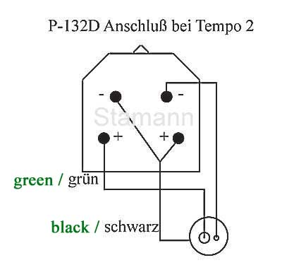
Bei der Tempo II muss ein Kanal am Tonsystem phasenvertauscht angeschlossen werden. Das hängt mit der Eigenart des Tempo-2-Verstärkers zusammen, bei dem für die Summenbildung der Gerätelautsprecher das Signal eines Kanals invertiert vorliegen muß. Siehe Eigenart. Bsp. für den Anschluß eines Pfanstiehl P-132D bei einer Tempo 2 (Rock-Ola 1478 und 485) |
With the Tempo II, one channel of the cartridge must be connected phase inverted. This is due to the special characteristic of the Tempo 2 amplifier, where the signal of one channel must be inverted for the summation of the cabinet speakers. See characteristic. Example of connection Pfanstiehl P-132D to Tempo 2 (Rock-Ola 1478 and 1485) |
|
|
|
||
|
Hinweis: dies ist nur bei Tempo II so, ab der Regis wurde das geändert - siehe hier. |
Note: This is only valid for Tempo II, it was changed with model Regis - see here. |
|
Diese Lampe - GE#313 -
befindet sich in den Verstärkern der Rock-Ola Modelle 453, 454, 456,
457, 459, 460, 461, 463, 464, 465, 466, 467, 469, 470, 471, 473 und 474.
Laut Schaltplan leuchtet sie im normalen Verstärkerbetrieb schwach. Ein
helles Leuchten dagegen deutet auf eine Überlastung der Lautsprecher
hin.
Aus dem Schaltplan: "Lamp is lit dimmly during normal amp. operation.
Lamp lit brightly indicates shorted output or improper speaker hookup.
See back door for speak inst. guide."
This lamp - GE#313 - is located
in the amplifiers of the Rock-Ola models 453, 454, 456, 457, 459, 460,
461, 463, 464, 465, 466, 467, 469, 470, 471, 473 and 474. According to
the schematic, it glows dimly in regular amplifier operation.
A bright light on the other hand, indicates that the speakers are
overloaded.
From the circuit diagram: “Lamp is lit dimmly during normal amp.
operation. Lamp lit brightly indicates shorted output or improper
speaker hookup. See back door for speak inst. guide."
Nach dem Abspielen von 2-3 Singles geht mit gewisser Regelmäßigkeit die Speaker Overload-Lampe an und der Ton verstummt. Was könnte die Ursache sein?
After playing 2-3 records, with some kind of regularity the speaker overload light lights up and the sound stops. What could be the cause of this?
Die Overload-Lampe leuchtet normalerweise
auf, wenn der Verstärkerausgang überlastet ist. Dies könnte zum Beispiel
durch falsch angeschlossene Lautsprecher oder durch einen Kurzschluss auf
den Lautsprecherklemmen entstehen.
Es kommt auch manchmal vor, dass Zusatzlautsprecher angeschlossen waren,
und die Kabel wurden nur abgeschnitten und hängen noch immer in der
Musikbox
herum und verursachen einen Kurzschluss. Wenn alles korrekt angeschlossen
ist, könnte auch ein Defekt im Verstärker die Ursache sein.
Die Speaker Overload-Lampe liegt im
Stromkreis der Gleichrichterschaltung für die Versorgung der
Vorstufen-ICs (+15 V und -15V). Daher leuchtet sie im Normalbetrieb
schwach.
Bei einer Überlastung des Ausgangs wird die Schaltung mit Q9 aktiviert
und der Thyristor SCR1 zündet. Dadurch wird das Relais K2 betätigt und
dieses schließt die Gleichrichterschaltung kurz. Dadurch liegt die volle
Spannung auf der Overload-Lampe, und sie leuchtet mit voller Helligkeit.
Gleichzeitig wird durch das Fehlen der Betriebsspannung der ICs das
Tonsignal unterbrochen, so dass die Endstufe nicht mehr angesteuert wird
und daher vor Schaden bewahrt wird. Wenn die Schaltung einmal
angesprochen hat, bleibt der Ton bis zum nächsten Plattenwechsel, also
wenn das Mute-Relay betätigt wird, abgeschaltet.
The overload lamp normally lights
up when the amplifier output is overloaded. This could be caused, for
example, by incorrectly connected speakers or a short circuit on the
speaker terminals.
It also sometimes happens that additional speakers have been connected
and the cables have only been cut and are still hanging around inside
the jukebox causing a short circuit. If everything is connected
correctly, a fault in the amplifier could also be the cause.
The speaker overload lamp is in
the circuit of the rectifier circuit for supplying the preamp ICs (+15 V
and -15 V). It therefore lights up dimly in normal operation.
If the output is overloaded, the circuit is activated with Q9 and the
thyristor SCR1 fires. This activates relay K2, which short-circuits the
rectifier circuit. As a result, the full voltage is applied to the
overload lamp and it lights up at full brightness. At the same time, the
absence of the operating voltage of the ICs interrupts the audio signal
so that the output stage is no longer driven and is therefore protected
from damage. Once the circuit has responded, the sound remains switched
off until the next record change, i.e. when the mute relay is activated.
Die Rock-Ola MAX Verstärker
52280-A leiden vor allem unter zwei Dingen: kalte Lötstellen und
trockene Elkos. Vorgehen:
Verstärker aufklappen und in der Frontklappe die linke Platine anpeilen.
Hier befindet sich die Spannungsaufbereitung für die Op Verstärker IC's.
Im wesentlichen sind da vier 100uf/40V radial und zwei 22uF/75V radial
zu ersetzen. Die beiden Zener Dioden, die mittig sitzen, nachlöten -
ebenso die Anschlussleiste.
Rückwand rechts die beiden Treiber Platinen: Insgesamt vier Elkos je
Platine sind zu ersetzen. Die Werte sind alle zu bekommen, wenn auch ein
wenig aus der Norm geschlagen. Ganz wichtig hier ist, die lange
Stecklerleiste und den zweipoligen NF Input Stecker nachzulöten. Hier
muss man ein bisschen vorsichtig sein, sonst lötet man sich diesen
schnell aus, da er ja nur zwei Lötstellen hat und die Abkühlzeit bei
dementsprechenden Lötkolben gern falsch eingeschätzt wird. Ebenso sind
der rote und der grüne Transistor nachzulöten. Der Rest bereitet idr.
keine Probleme.
Platine Rückwand linke Seite: Alle drei Stecker sorgfältig nachlöten.
Vorsichtig hier bei dem 8 poligen Stecker mittig. Diese sind oft
schlecht verarbeitet bzw. schlecht eingelötet. Wo das genaue Problem
liegt kann ich nicht einmal genau sagen. Es ist aber so das es hier oft
Lufteinschlüsse gibt. Rückt man der Lötstelle jetzt zu Leibe, dehnt sich
die Luft aus und der heiße Lötzinn kommt einem entgegen.
Wichtig wäre noch die Box heutzutage netzteiltechnisch auf 240V
umzujumpern. Das schont einfach Netzteil, Verstärker und Motoren.
Achtung: bei falscher Jumperung ist zuerst das Netzteil und mit ein
wenig Pech später die ganze Musikbox Schrott. In dem Zusammenhang sollte
auch die Prozessor Versorgungsspannung - violette Leitung 9,6V -
überprüft und ggf. eingestellt werden. Es ist aber unerlässlich, dass
der Verstärker neu abgeglichen wird. Wie das geht steht bebildert im
Handbuch ganz hinten erklärt.
Jetzt gibt es noch einen Punkt der in keiner Anleitung so erklärt steht:
Es gibt Verstärker früher Baureihen wo man eine Diode anfangs
weggelassen hat. bei diesen brummt die Kiste auch hörbar. Daher bitte im
Deckel des Verstärkers ziemlich mittig wo auch die Anschlussbuchse des
Lautstärkereglers ist einmal nachschauen. Hier befindet sich auf einen
Lötstützpunkt eine einzelne Diode. Ist diese verbaut ist alles in
Ordnung, fehlt sie brummt der Verstärker von Haus aus.
The Rock-Ola MAX amplifier
52280-A suffers from two main problems: Cold
solder joints and dry electrolytic capacitors. Procedure:
Open the amplifier and locate the left-hand circuit board in the front
door. This is where the voltage conditioning for the op amp ICs is
located. Essentially there are four 100uf/40V radial and two 22uF/75V
radial to be replaced.
Re-solder the two Zener diodes in the middle as well as the terminal
strip.
The two driver boards on the right rear panel: A total of four
electrolytic capacitors per board need to be replaced. The values are
all available, even if they are a little out of the norm. It is very
important to re-solder the long connector strip and the two-pin NF input
plug. You have to be a bit careful here, otherwise you will quickly
solder it out, as it only has two soldering points and the cool down
time is often misjudged with the corresponding soldering iron. The red
and green transistors must also be re-soldered. The rest usually causes
no problems.
Circuit board back left side: Carefully re-solder all three connectors.
Be careful here with the 8-pin connector in the middle. These are often
badly made or badly soldered. I can't even say exactly where the problem
lies. However, there are often air pockets here. If the solder joint is
now tackled, the air expands and the hot solder comes towards you.
These days, it would also be important to switch the power supply to
240V. This simply protects the power supply, amplifier and motors.
Caution: If the jumper is set incorrectly, the power supply will be the
first to go and, with a little bad luck, the whole jukebox will be
ruined. In this context, the processor supply voltage - purple line 9.6V
- should also be checked and adjusted if necessary.
However, it is essential that the amplifier is recalibrated. How to do
this is explained illustrated in the back of the service manual.
Now there is one more point that is not explained in any manual: There
are amplifiers from earlier series where a diode was omitted at the
beginning. Therefore, please take a look inside the cover of the
amplifier in the middle where the connection socket for the volume
control is located. There is a single diode on a soldering point here.
If this is installed, everything is fine; if it is missing, the
amplifier is humming by default.
Die Angaben haben keinen
Anspruch auf Vollständigkeit oder Richtigkeit.
Bei den (importierten) Boxen können im Laufe der Jahre durchaus
Veränderungen vorgenommen worden sein. Copyright.
Ein Service von

Copyright by
Stamann Musikboxen