|
Ab 1968 mit dem Modell LS3 - Apollo - verwendete
Seeburg in den 160er Modellen DCCs als Netzteil und ersetzte die bisherigen alpha-numerischen
Tastaturen durch eine digitale mit drei Ziffern. Diese Modelle verwenden
auch die sog. "Black (DTP1) and Gray Boxes" (DRD1) als Kredit- und
Empfängereinheiten. In der Gesamtheit nennt sich das System "Microlog".
Es gibt verschiedene DCCs: DCC1, DCC2, DCC3 und DCC4. Verwendung:
DCC1: LS3 Apollo, USC1 Bandshell,
DCC2: USC2 Bandshell Firestar,
DCC3: SPS160 Olympian, FC1 Regency
DCC4: SPS2 Matador, SQS2 Quad Matador, STD160 Vogue II, SQS160 Quadrophonic, STD2 Entertainer, SQS2
Quad Entertainer, STD3 Sunstar, SQS3 Quad Sunstar, STD4 Mardi Gras, SQS4
Quad Mardi Gras, FC2 Hutch
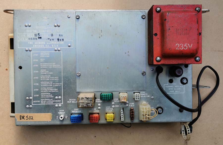
Enden die Typenbezeichnungen mit -H5, so sind sie für
235V ausgelegt, ansonsten für 117V. -5 weist auf Betrieb an 50 Hz. an, -56 auf die
Funktion mit 50 und 60 Hz. Zudem gibt es noch die Ergänzungen
Code A und Code B.
Ein wesentlicher Unterschied in den DCCs liegt im
Schaltkreis des jeweiligen Trip Relais.
DCC1, DCC11, DCC4, DCC41 und DCC42 verwenden ein
24VDC Relais, K3100, Seeburg Nr. 509802.
DCC2, DCC21, DCC3, DCC31, DCC32 und DCC33 verwenden ein 12VDC Relais, K3103, Seeburg Nr.
311367.
Die elektrischen Anschlüsse in den Relaissockeln sind für die 24VDC- und
12VDC-Relais bis auf die Positionsnummern identisch.
Bei DCC2 Code A befinden sich zwei Dioden an der Fassung, bei DCC2 Code
B ein großer 150 Ohm 2W Widerstand.
Bei den Versionen DCC32 und DCC42 werden die Spannungen -13 und -27V im
Gegensatz zu den anderen DCCs automatisch zusammen geführt.
Es ist möglich, die Relais unter Anpassung der Spannung untereinander zu
tauschen. Bei einer DCC2 Code A müssen dann jedoch die zwei Dioden
ersetzt werden, so dass auf Code B aufgerüstet wird. Sonst kann es zu
falschen Wahlen kommen (meistens ein oder zwei Nummern nach der Wahl).
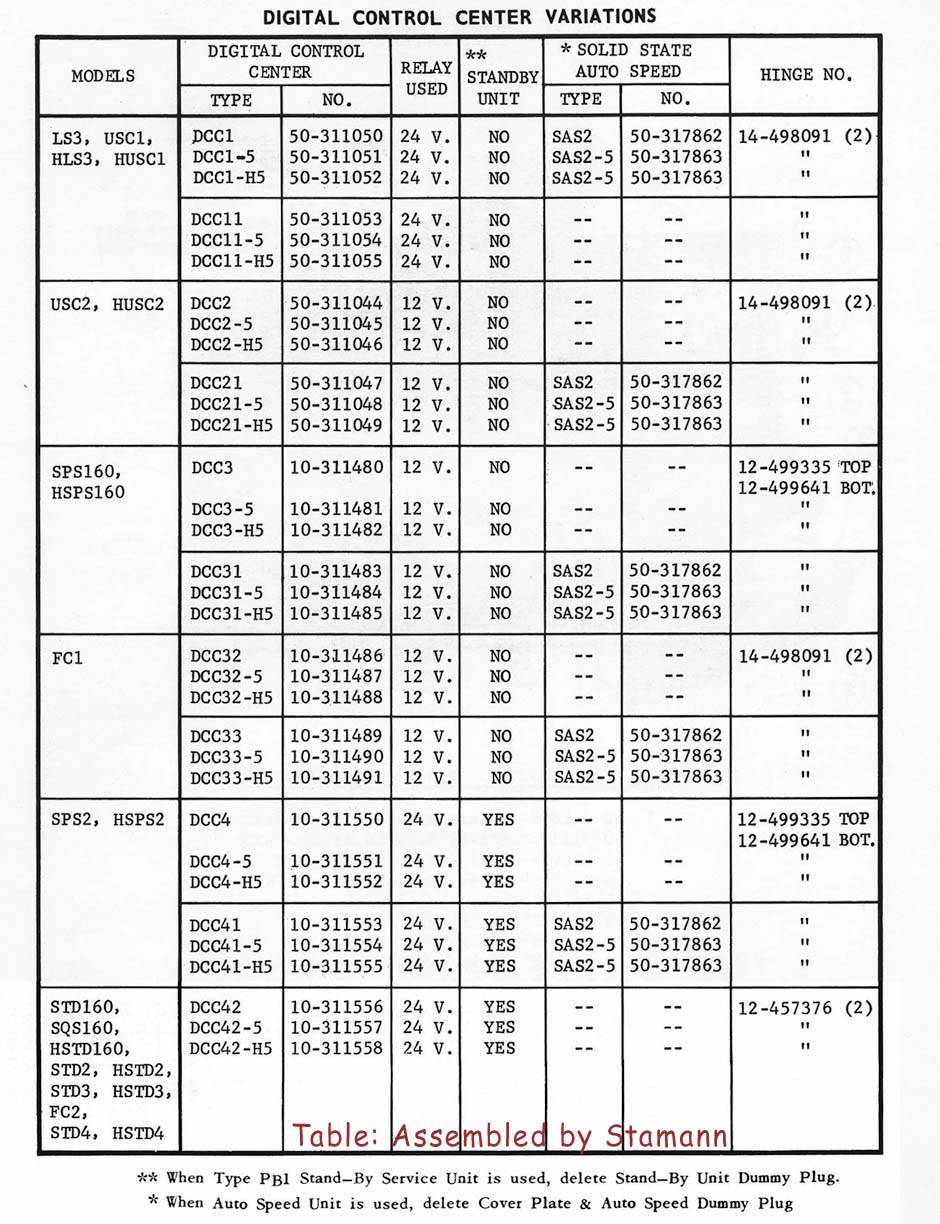
Nachfolgend eine Übersicht über alle DCC Variationen: |
|
Starting in 1968 with model LS3
- Apollo, Seeburg used in their 160 selection models DCCs as power supplies and replaced the previous
alphanumeric keyboards with a three-digit digital keyboard. These models
also use the so-called Black (DTP1) and Gray Boxes (DRD1) as credit and
receiver units. The system as a whole was called “Microlog.”
There are various DCCs: DCC1,
DCC2, DCC3, and DCC4. For use in:
DCC1: LS3 Apollo, USC1 Bandshell,
DCC2: USC2 Bandshell Firestar,
DCC3: SPS160 Olympian, FC1 Regency
DCC4: SPS2 Matador, SQS2 Quad Matador, STD160 Vogue II, SQS160 Quadrophonic, STD2 Entertainer, SQS2
Quad Entertainer, STD3 Sunstar, SQS3 Quad Sunstar, STD4 Mardi Gras, SQS4
Quad Mardi Gras, FC2 Hutch
If the model type ends with
-H5, they are designed for 235V, otherwise for 117V. The suffix -5
refers to 50 Hz operation while -56
indicates operation both at 50 and 60 Hz. There are also the extensions Code
A and Code B.
A significant difference in the
DCCs can be found in the circuitry of each trip relay.
DCC1, DCC4, DCC41, and DCC42 use a
24VDC relay, K3100, Seeburg No. 509802.
DCC2, DCC3, DCC31, DCC32, and DCC33 use a 12VDC relay, K3103, Seeburg No. 311367.
The electrical connections to the relay sockets are the same for the
24VDC and 12VDC relays except for the callout numbers.
DCC2 Code A has two diodes on the socket, while DCC2 Code B has a large
150 Ohm 2W resistor.
In the DCC32 and DCC42 versions, the -13 and -27V voltages are
automatically "tracked" together, unlike in the other DCCs.
It is possible to interchange the relays if the voltage is adjusted
accordingly. However, with a DCC2 Code A, the diodes needs to be
replaced so that it is upgraded to Code B. Otherwise, incorrect
selections may occur - mostly one or two numbers past selected
record). Following a
table with all DCC variations: |