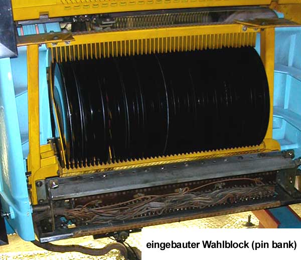
In der Pin-Bank
sind zwei Reihen mit jeweils 50 mechanischen Schaltern angeordnet. Eine
Reihe für die A-Seiten und eine für die B-Seiten. Jedes Hebelchen hat
einen kleinen Elektromagneten, durch den es in die „Ausgewählt-Position“
gesetzt werden kann. Zurückgesetzt wird es von einem Hubmagneten, der
mit dem Abspielmechanismus verbunden ist und zusammen mit diesem von
Platte zu Platte fährt.
Sobald ein Pin ausgewählt ist, aktiviert er ein Relais im Selection
Receiver, das dafür sorgt, dass der Mechanismus losläuft. Erst wenn der
letzte Pin wieder zurückgesetzt ist, bleibt der Mechanismus stehen. Wenn
der Mechanismus auf einen ausgewählten Pin trifft (er schließt dann
einen elektrischen Kontakt), wechselt er in den Abspielmodus und greift
die entsprechende Platte.
Zur Funktion: Wie in diesem Forum schon öfters zu lesen war, sind die 100 Auswahlen bei diesen Jukeboxen in einer 20 x 5 Matrix angeordnet. Es gibt 5 Kontaktblöcke mit jeweils 20 Kontakten. Damit ein Hebel gesetzt wird, muss über die entsprechende Magnetspule ein Strom von einer Spannungsquelle nach Masse fließen (und zwar nur über diese eine). Auf der Primärseite (Spannungsquelle) ist daher immer jede 20. Spule miteinander verbunden (also z.B. Spule 1 mit 21, 41, 61 und 81). Sekundärseitig (Masse) werden über den Kontaktblock jeweils 20 Spulen miteinander verbunden (also z.B. 1 bis 20). Eine bestimmte Tastenkombination sorgt dafür, dass jeweils ein bestimmter Block von 20 Spulen an Masse gelegt wird und eine dieser Spulen primärseitig an die Spannungsversorgung (4 andere Spulen natürlich auch, aber die sind sekundärseitig nicht mit Masse verbunden, und daher nicht von Strom durchflossen). Somit wird bei jeder Tastenkombination genau ein Hebel gesetzt.
Two rows of 50 mechanical
switches are arranged in the pin bank. One row for the A-sides and one
for the B-sides. Each lever has a small electromagnet that can be used
to set it to the "selected" position. It is reset by a lifting magnet,
which is connected to the mechanism and moves together with it from
record to record.
As soon as a pin is selected, it activates a relay in the selection
receiver, which ensures that the mechanism starts running. The mechanism
only stops when the last pin is reset. When the mechanism hits a
selected pin (it then closes an electrical contact), it switches to
playing mode and picks up the corresponding record.
Function: As you have often read in this forum, the 100 selections on these jukeboxes are arranged in a 20 x 5 matrix. There are 5 contact blocks with 20 contacts each. For a lever to be set, a current must flow from a voltage source to earth via the corresponding solenoid coil (and only via this one). On the primary side (voltage source), every 20th coil is therefore always connected to each other (e.g. coil 1 with 21, 41, 61 and 81). On the secondary side (earth), 20 coils are connected to each other via the contact block (e.g. 1 to 20). A specific pushbutton combination ensures that a specific block of 20 coils is connected to earth and one of these coils is connected to the power supply on the primary side (4 other coils are also connected to earth on the secondary side, of course, but they are not connected to earth and therefore no current flows through them. This means that exactly one lever is set for each key combination.
1. Beim Auswählen wird
der entsprechende Pin nicht gesetzt.
Das kann daran liegen, dass der Elektromagnet defekt ist (das kann man
messen), oder dass der Pin zu schwer geht (das ist nach meiner Erfahrung
nicht unbedingt fühlbar und auch nur sehr schwer messbar). Bei diesem
Fehler kann es passieren, dass der Fehler manchmal auftaucht und
manchmal nicht.
2. Bestimmte Pinne werden zwar ausgewählt, haben aber keinen guten
Kontakt (das Relais im Selection Receiver wird nicht aktiviert).
Bei diesem Fehler kann es z.B. passieren, dass eine Platte ausgewählt
wird und nichts passiert. Wird dann eine zweite Platte ausgewählt,
werden beide abgespielt. Es kann auch sein, dass die zuletzt gewählte Platte nicht mehr abgespielt wird.
Abhilfe:
Zunächst sollten die Kontakte der Pin-Bank auf ihre Funktion getestet
werden. Dafür kann man mit einem Durchgangsprüfer den Kontakt zwischen
dem Gehäuse der Pin-Bank und jedem einzelnen Kontakt an der Seite der
Pin-Bank (ich meine die Kontaktzungen, die von den vertikal beweglichen
20-fach Kontaktblöcken oben unter der Abdeckung der Pin-Bank an Masse
gelegt werden) messen, wenn der jeweilige Kontaktblock (von Hand) bis
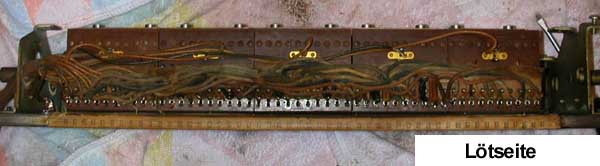
zum Anschlag heruntergedrückt wird. An jedem Kontaktblock ist ein Kabel
angelötet (das Kabel verbindet die Kontaktblöcke mit Masse). Diese
Lötstelle ist relativ oft gebrochen. Darauf sollte man also auf jeden
Fall achten. Wichtig ist, die Pin-Bank Kontakte nicht zu schmieren.
Sind die Kontakte in Ordnung, muss man die Pin-Bank zerlegen, reinigen
und wieder zusammenbauen. Diese Arbeit gilt als schwierig und kann ca. 5
bis 8 Stunden dauern. Man kann diese Arbeit schlecht unterbrechen, denn
es sind viele kleine Teile beteiligt für die man so leicht keinen Ersatz
bekommt.
Einen ausführlichen Bericht zum Zerlegen und Zusammenbauen finden Sie hier: Pinbank 100G
1. The corresponding pin is not
set when selecting.
This may be because the electromagnet is defective (this can be measured),
or because the pin is too hard to move (in my experience, this cannot
necessarily be felt and is also very difficult to measure). With this
error, it can happen that the error sometimes occurs and sometimes not.
2. Certain pins are selected
but do not have a good contact (the relay in the selection receiver is
not activated).
With this error it can happen, for example, that a record is selected
and nothing happens. If a second record is then selected, both records
are played. It is also possible that the last record selected is no
longer played.
Remedy:
Firstly, the contacts of the pin bank should be tested for function. To
do this, you can use a continuity tester to measure the contact between
the housing of the pin bank and each individual contact on the side of
the pin bank (I mean the contact tongues that are connected to earth
from the vertically movable 20-way contact blocks at the top under the
cover of the pin bank) when the respective contact block is pressed down
(by hand) as far as it will go. A cable is soldered to each contact
block (the cable connects the contact blocks to earth). This solder
joint is relatively often broken. You should therefore pay attention to
this in any case. It is important not to lubricate the pin bank contacts.
If the contacts are OK, the pin bank must be dismantled, cleaned and
reassembled. This work is considered difficult and can take around 5 to
8 hours. It is difficult to interrupt this work as there are many small
parts involved for which it is not easy to find replacements.
You can find a detailed report on disassembly and reassembly here: Pinbank 100G
|
Meine Musikbox wählte nicht alle Platten, es wurden verschiedene Wahlen nicht gemacht, dabei waren es nicht nur Fehlwahlen wie z.B. alle der Taste F, G oder nur alle 1, 3, 4 oder ähnlich. Nein willkürlich, ohne einen Zusammenhang bestimmter Zahlen oder Buchstaben. Zunächst habe ich alle Kontakte der Tastatur gereinigt und wo nötig justiert. Das war nicht die Ursache, also weiter. Alle Steckverbindungen, die auf das Netzteil gehen, überprüft und auch diese Kontakte an den Steckern gereinigt. Auch das hat nichts gebracht. Weiter habe ich das Netzteil (Stepper) und das Kreditgerät (sitzt auch auf dem Netzteil) durchgesehen, alle Kontakte gesäubert und auch justiert. Das hatte auch nicht den gewünschten Effekt. Da war guter Rat teuer, was nun? Habe mein Problem hier im Forum berichtet und es kam eine Menge Feedback. Es soll an der Pinbank liegen, diese sitzt auf der Rückseite der Musikbox hinter den Schallplatten. |
My jukebox did not select all records, various selections were not made, and not just incorrect selections such as all the F, G or only all 1, 3, 4 or similar. No, it was random, without any comprehensible context between certain numbers or letters. First I cleaned all the contacts on the keyboard and adjusted them if necessary. That was not the cause, so l continued. I checked all the plug connections going to the power supply and also cleaned these contacts on the plugs. That didn't help either. I then checked the power supply (stepper) and the credit unit (also located on the power supply), cleaned all contacts and adjusted them. That didn't have the desired effect either. Good advice was expensive, what now? I reported my problem here in the forum and there was a lot of feedback. The problem is said to be the pin bank, which is located on the back of the jukebox behind the records. |
|
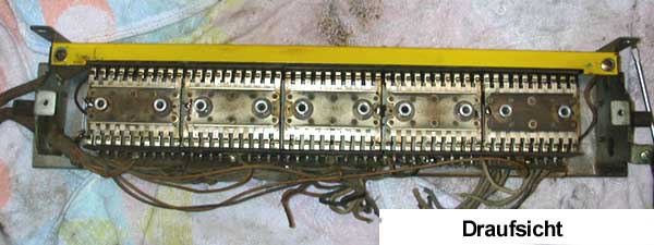
OK, dann erst einmal ausbauen, habe die Pinbank dann einfach so angeschlossen und auf den Boden gelegt. Zum Testen habe ich den Scan Schalter umgelegt, so das die Maschine nicht losfährt, aber Wahlen gemacht werden. Hier konnte ich erneut feststellen, es wird einfach nicht alles gewählt. |
OK, then I removed it first, simply connected the pin bank and placed it on the floor. To test this, I flipped the scan switch so that the mechanism would not start, but would make selections. Here I noticed again that nothing gets selected. |
|
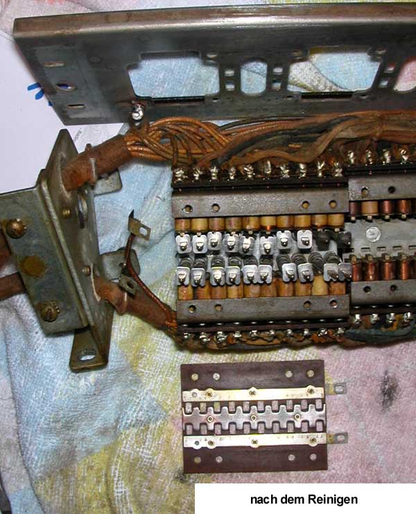
Ich habe dann die Pinbank von oben her aufgeschraubt und die 5 x 20 Kontakte gründlich mit Reinigungsbenzin gesäubert (2 Sprengringe halten die Kontakte) das wurde auch wohl Zeit, denn diese waren sehr verdreckt. An dieser Stelle sollte man aufpassen, ob auf jedem der 5 Blöcke jeweils ein Kabel von (oben drauf gesehen) angelötet ist. Ich fand zwei, die locker waren. Also alles wieder anlöten und zusammengebaut. Habe wieder die Pinbank auf den Boden gelegt und angeschlossen. So, wieder getestet - aber das war auch nicht die Lösung. Was jetzt folgt, dauerte mit Sicherheit 8 oder 9 Stunden mit voller Konzentration, damit nichts verloren oder übersehen wurde. |
I then unscrewed the pin bank from the top and cleaned the 5 x 20 contacts thoroughly with cleaning solvent (2 snap rings each hold the contacts), which was probably about time as they were already very dirty. At this point you should check whether there is a cable soldered to each of the 5 blocks (seen from above). I found two that were loose. So I re-soldered all and re-assembled it. I put the pin bank on the floor again and connected it. So, tested again, but that wasn't the solution either. What follows now certainly took 8 or 9 hours with full concentration so that nothing got lost or overlooked. |
|
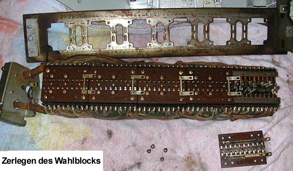
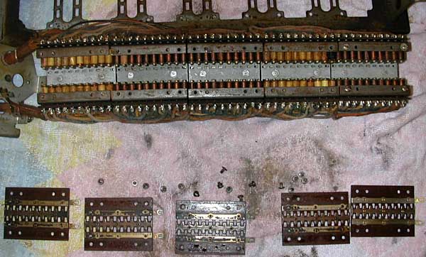
Jetzt bin ich der Pinbank von unten angegangen. Zunächst die
Rahmenplatte vom Chassis entfernt, so das 5 „Pertinaxplatten“ zu sehen
waren. Ich habe zunächst die Verbindung der Leiterplatten abgeschraubt.
Jeweils 2 Schräubchen, danach an einem „Block“, 4 Schrauben gelöst -
Vorsicht, die Platine steht unter (Feder) Spannung. Die Platte kann man
abheben und zum Vorschein kommen 20 Hebel mit jeweils einer Feder und
einer kleinen rechteckigen Metallplatte (Kontaktniete). Kontrolle, ob
tatsächlich alle 20 Kontaktnieten aufliegen, damit nichts verloren geht. |
Now I approached the
pin bank from underneath. First, I removed the frame from the
chassis so that 5 "Pertinax plates" were visible. I first
unscrewed the connection of the circuit boards. I unscrewed 2
screws at a time, then 4 screws on a "block" - be careful, the
circuit board is under (spring) tension. The board can be lifted
off to reveal 20 levers, each with a spring and a small
rectangular metal plate (contact rivet). Check that all 20
contact rivets are actually in place so that nothing will get
lost. |
|
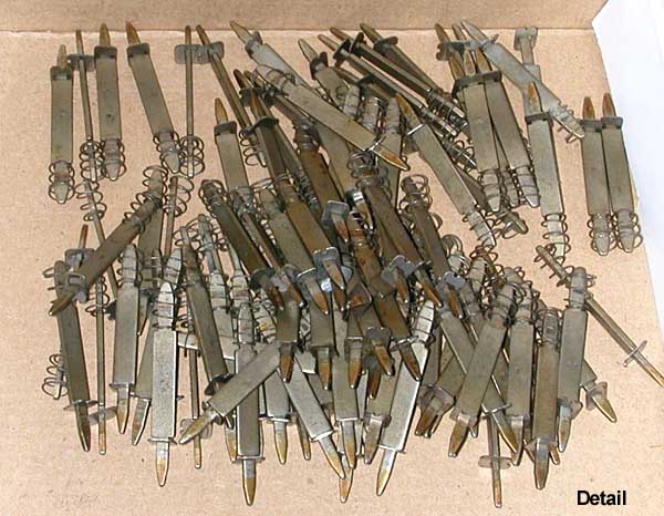
Diese Prozedur habe ich an allen Blöcken ausgeführt und die 100 Pinne einzeln heraus gezogen und beim Einlegen in Reinigungsbenzin darauf geachtet, das sie immer komplett sind. (Ich hatte immer Angst, die Kontaktnieten zu verlieren.) Nun war die Pinbank "leer". |
I completed this procedure on all the blocks and pulled out all 100 pins one by one, making sure that they stay always complete when soaking them in white spirit. (I was always afraid of losing the contact rivets.) Now the pin bank was "empty". |
|
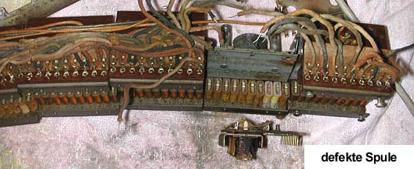
Alles, was ich sehen konnte, wurde gereinigt. Mit dem Messgerät auf 200 Ohm gestellt habe ich alle 100 Spulen gemessen. Vorsicht, dass kein Drähtchen von der Spule beim Hantieren mit dem Messgerät abgerissen wird. Ein Draht liegt unter einer Pappabdeckung, der andere ist mit 2 Kabeln angelötet, als Kontakt. Dabei habe ich eine defekte Spule ermitteln können weil sie völlig andere Ohmwerte aufwies. Auch eine Sichtprüfung hat die angekohlte Spule als Täter übermittelt. Wie gesagt, es war eine Spule, die defekt war. |
Everything I could see was cleaned. With a measuring unit set to 200 Ohm I measured all 100 coils. Be careful not to tear off any wires from the coil when handling with the multimeter. One wire is below a cardboard cover, the other is soldered on with 2 cables as a contact. I was able to identify a defective coil because it had completely different ohm values. A visual inspection also revealed the charred coil as the causert. As I said, it was a coil that was defective. |
|
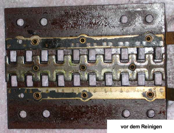
OK, dann muss sie halt ersetzt werden. Leicht gesagt, denn nun muss wieder der obere Kontaktblock (20 Kontakte, die ich am Anfang schon gesäubert hatte), gelöst werden, weil die Spulen von dort mit 2 Schrauben gehalten werden. Außerdem ist der dortige „Gruppenmagnet“ auch an 2 Kabeln angelötet - also ablöten, sonst wird es nichts. Alle anderen 20 Kabel die an die Spulen gehen, müssen auch abgelötet werden. Das hört sich schlimm an, ist es aber nicht, weil man das System leicht erkennen kann. (Z.B. K9 ist mit H9, F9, D9 und B9 verbunden, alle weiteren Zahlen dementsprechend auch.) Jetzt endlich hatte ich 10 Spulen auf einem Träger in der Hand und musste nur noch die Defekte auslöten. Aber Achtung, es sind immer 2 Spulen mit einer „Speednut" (Klemme) versehen und die gehen echt schwer ab. Danach aber ging die Spule gut heraus. Jetzt erst mal eine Suchanzeige starten und während der Wartezeit habe ich alles andere gesäubert. Bei den „Pins“ bin ich einzeln vorgegangen. Die Kontaktnieten haben eine polierte Seite, diese zeigt zur „Pertinaxplatine“. Schön blank poliert mit einem Pinsel und Wattestäbchen gingen alle Ansätze gut ab. Eine Niete hatte eine Art „Verkohlung“ und hatte dadurch eine „Beule“ also auch hierfür Ersatz suchen. Nun noch die 5 „Pertinaxplatten" reinigen. Sie haben 2 durchgehende Leiterbahnen, die habe ich auch vom Schmutz befreit und in der Mitte geht die Führung für die Kontaktnieten durch, also diese besonders gut reinigen, damit die Kontaktnieten auch guten Kontakt bekommen. |
OK, then it just has to be replaced. Easy to say, because now the upper contact block (20 contacts, which I had already cleaned at the beginning) has to be loosened again, because the coils are held there with 2 screws. In addition, the "group magnet" there is also soldered to 2 cables - so unsolder it, otherwise it won't work. All the other 20 cables that go to the coils must also be desoldered. That sounds bad, but it is not, because you can easily recognize the system. (E.g. K9 is connected to H9, F9, D9 and B9, all other numbers accordingly). Now I finally had 10 coils on a carrier in my hand and only had to desolder the defective ones. But be careful, there are always 2 coils fixed with a speed nut (clamp) and they are really difficult to remove. After that, however, the coil came out easily. First of all, I placed
a
wanted ad and while I was waiting I cleaned everything else.
I proceeded one by one with the pins. The contact rivets have a
polished side, which faces the pertinax board. Nicely polished
with a brush and cotton buds, all of the rivets came off well.
One rivet had a kind of "charring" and therefore had a "dent",
so I had to find a replacement for this too. Now clean the 5 pertinax boards. They have 2 continuous conductor tracks, which I also cleaned of the dirt, and the guide for the contact rivets goes through the middle, so clean these particularly well so that the contact rivets also make good contact. |
|
Jetzt kam das mir angekündigte „Kniffelige" zusammenbauen. Ich habe
immer einen Pin komplett zusammengestellt, noch einmal die Kontaktniete
mit einem Wattestäbchen gesäubert und dann im ersten Block eingesetzt,
am besten immer einen oben und dann einen darunter einsetzen. Ich fand
heraus, dass alle in
einer Reihe und dann die nächste Reihe nehmend nicht wirklich klappt,
weil man sehr kleine Finger bräuchte. Also aufpassen, dass die
polierte Seite der Kontaktniete oben ist und die Kerbung immer zu den
Spulen zeigt. Alle 20 Pinne eingesetzt und eine Endkontrolle gemacht, ob
wirklich alle in der richtigen Position mit der Kerbung und der
polierten Kontaktniete sitzen. Danach die "Pertinaxplatte" mit Gefühl
aufsetzen und darauf achten, das alle 20 Pins durch die dafür
vorgesehenen Öffnungen kommen. Mit etwas Druck auf die Platte die 4
Schrauben (das sind die 4 Äußeren auf der Platte) wieder anziehen. An
dieser Stelle habe ich einen Funktionstest gemacht, ob die Kontaktnieten
auch mit der Pertinaxplatte Kontakten. Also ein Kabel vom Messgerät an
die äußere Kontaktbahn angeschlossen (das sind die 2 Anschlüsse die von
Block zu Block gebrückt werden und von oben zu sehen sind) und mit der
Krokodilklemme an einen Pin und diesen dann zur Mitte bewegt, alle 20
Pinne habe ich so „durchgeklingelt", ob Kontakt ist. Hier gab es nichts
zu beanstanden, die sauberen Kontakte gehen ab wie Schmitz Katze. Habe
dann meine neue Spule eingelötet und auch eine neue Kontaktniete
eingesetzt. (Der Ersatz war allerdings nicht blank poliert, sonder
Kupferfarben und blank.) Somit konnte ich auch den letzten Block wieder
herstellen. Alles wieder zusammengebaut und außerhalb der Box erst
einmal getestet. Alles was ich so wählte funktionierte.
Guter Dinge habe ich dann die Pinbank wieder in die Box gebaut.
Soweit meine Erfahrungen mit der Pinbank, alles in allem kann man das
Teil gut abbauen und auch reinigen, da ist im Lauf der Zeit doch schon
viel Dreck und Anhaftungen zusammen gekommen. Nur denkt daran, es geht
nicht sehr schnell und aufpassen das nichts verloren geht.
Viel Erfolg wünscht euch, Ralf F. |
Now came the "tricky"
assembling I had been told about. I always assembled one pin
completely, cleaned the contact rivets once again with a cotton
bud and then inserted them in the first block - preferably
always inserting one at the top and then one underneath. I
realized that all in one row and then doing the next row,
doesn't really work because you would need very small fingers.
So make sure that the polished side of the contact rivet is on
top and the notch always faces the coils. Insert all 20 pins and
carry out a final check to ensure that they are all in the
correct position with the notch and the polished contact rivet.
Then put on the pertinax board carefully and make sure that all
20 pins come through the openings provided. Tighten the 4 screws
(these are the 4 outer screws on the board) with a little
pressure on the board. At this point, I carried out a functional
test to check whether the contact rivets also make contact with
the pertinax board. In good spirits, I then put the pin bench back in the box. So far my experience with the pin bank, all in all you can easily dismantle and clean the assembly, as a lot of dirt and adhesions have accumulated over time. Just remember that it doesn't go very quickly and be careful not to lose anything. Ralf F. wishes you great success. |
Die Angaben haben keinen
Anspruch auf Vollständigkeit oder Richtigkeit.
Bei den (importierten) Boxen können im Laufe der Jahre durchaus
Veränderungen vorgenommen worden sein. Copyright.
Copyright by Stamann Musikboxen