|
Die Wurlitzer 1100 (Baujahr 1948) war die erste Box aus dem Hause
Wurlitzer, die einen Anschluss für Zusatzlautsprecher ab Werk besaß.
Alle Jukeboxen vorher benötigten einen sogenannten Fader-Adapter.
Es gab zwei Typen:
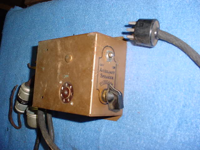
1. Single
Fader-Adapter
für den Anschluss eines 8 Ohm Zusatzlautsprechers (oder zwei 3.5 Ohm
Zusatzlautsprechers in Reihenschaltung). |
|
The Wurlitzer 1100 (built in
1948) was the first Wurlitzer jukebox to have a connection for
additional loudspeakers ex works. All previous jukeboxes required a
so-called fader adapter.
There were two types:
1. Single Fader Adapter
For connecting an 8 Ohm additional speaker (or two 3.5 Ohm additional
speakers in series). |
|
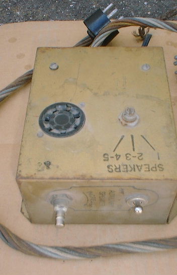
2. Multiple
Fader-Adapter
zum Anschluss von bis zu fünf 8 Ohm Zusatzlautsprechern.
Auf diesem
Fader gab es einen Umschalter mit den Stellungen "1" oder "2-3" oder
"4-5. Die Anpassung der jeweiligen Lautsprecherlasten erfolgte über
Anzapfungen eines eingebauten Übertragers. |
|
2. Multiple Fader Adapter
For connecting up to five additional 8 Ohm extra speakers.
On this fader there was a switch with the positions "1" or "2-3" or
"4-5". The respective extra loudspeaker loads were adjusted via taps of
a built-in transformer. |
|
Beide Varianten des Fader-Adapters wurden zwischen Verstärker und
Innenlautsprecher der Jukebox geschaltet.
Es wurde also der Innenlautsprecher der Jukebox vom Verstärker getrennt,
der Fader-Adapter am Lautsprecheranschluss des Verstärkers und der
Innenlautsprecher an einer Buchse des Fader-Adapters angeschlossen.
Am Fader-Adapter befanden sich ein ON-OFF-Schalter (Zusatzlautsprecher
EIN oder AUS) und ein Lastregler, mit dem man die Lautstärkenverteilung
zwischen Jukeboxinnenlautsprecher und Zusatzlautsprecher regeln konnte.
Fader-Adapter kann man im Internet in den USA finden, aber meist sind
sie optisch nicht gut erhalten und der 8-polige Lautsprecherstecker oder
gleich das ganze stoffummantelte Kabel sind abgeschnitten.
Das zweiadrige Kabel für den Zusatzlautsprecher ist immer brüchig und
muss ersetzt werden.
Es gibt drei optisch unterschiedliche Varianten:
-
goldenes Gehäuse
mit "antikem" Schriftbild (Vorkriegszeit, möglicherweise
dreißiger Jahre)
-
goldenes Gehäuse
mit druckbuchstabenähnlicher Schrift (Vorkriegszeit,
möglicherweise vierziger Jahre)
-
rotes Gehäuse mit
druckbuchstabenähnlicher Schrift (ab W750 bis zur W1015 und W1080)
Die Beschaltung des
Lautsprechersteckers (7-polig) hat Wurlitzer von Beginn an immer gleich
belegt, obwohl sich die Widerstandswerte der Feldspulen und auch der
Schwingspulen zwischen 1935 und 1947 etwas geändert haben.
Die Feldspulen waren immer an den beiden "dicken" Stiften (# 1 und # 7)
angeschlossen, die Schwingspule des Lautsprechers war immer an Pin # 4
und Pin # 5 angeschlossen. Somit sind auch die Fader universell
verwendbar, sogar in den Countermodellen.
An den Fadern wurden die
Zusatzlautsprecher über einen 5-poligen Stecker angeschlossen und mit
einer Art metallenem Überwurfgehäuse gesichert, welches genau über die
Stecker paßte und aus zwei Teilen verschraubt wurde (um das
unbeabsichtigte Auftrennen der Steckverbindung zu verhindern).
In der Regel findet man aber die Fader ohne jene 5-polige
Steckverbindung und das metallene Überwurfgehäuse ist so gut wie gar
nicht zu finden.
Auf dem obigen Bild vom Single-Fader kann man den 5-poligern Stecker und
auch eine Hälfte des Überwurfgehäuses erkennen.
Zum korrekten Anschluss
des Lastreglers (egal ob 8/40 Ohm oder 3.5/17 Ohm):
Jeder Lastregler hat drei Anschlüsse: einen für den Schleifer (in der
Mitte) sowie je einen für die beiden Drahtwicklungen mit einem
höherohmigen (40 bzw. 17 Ohm) und einem niederohmigen ( 8 bzw. 3.5 Ohm)
Anschluss (jeweils außen rechts und links).
Der Lautsprecher (8 bzw. 3.5 Ohm) wird mit seinen beiden Leitungen am
Schleifer und am höherohmigen Anschluss angelötet.
Die Zuleitungen vom Verstärker (Fader) werden jeweils am höherohmigen
und niederohmigen Anschluss angelötet.
Sinn des Lastreglers ist es, dem Verstärker eine konstante Belastung
vorzugaukeln, obwohl die Lautstärke am Zusatzlautsprecher
heruntergeregelt wird (Überschuss wird über den Widerstandsdraht des
Lastreglers in Wärme umgesetzt).
Die Gesamtlautstärke des Systems "Jukebox - Zusatzlautsprecher" wird an
dem Lautstärkeregler des Verstärkers geregelt und grundsätzlich
bestimmt. Die Verteilung der Lautstärkeverhältnisse zwischen Jukebox und
Zusatzlautsprecher wird am Fader geregelt und am Lastregler im
Zusatzlautsprecher kann man dann den Zusatzlautsprecher noch weiter
herunterregeln (nur leiser....!!).
Die Schaltung der beiden
Fader-Adapter sind in der W 1015 Anleitung ausführlich dokumentiert.
Auch in der Anleitung zum Wurlitzer Modell 50 wird die Verwendung des
Single - bzw. Multiple Fader ausführlich beschrieben. Er war also zu
dieser Zeit - 1938 - (evtl. neu) verfügbar.
Single Fader-Adapter
bekommt man im Internet unrestauriert in dem oben beschriebenen Zustand
von ca. US$ 80.00 bis US$ 150.00 (Stand 06/2009); die viel seltenere
Multiple Fader Variante evtl. ab US$ 130 bis über US$ 200, eben je nach
Erhaltungszustand.
Ich habe für NOS Multiple Fader auch schon (gerne) US$ 350 bezahlt.
Einbau in frühe
Modelle, Wurlitzer 312, 616 u.a:
Ganz frühe Wurlitzermodelle hatten in der Junctionbox Öffnungen, in die
man die Komponenten (ON-OFF und Überblendregler) eines Faders
nachträglich einbauen konnte.
616: vermutlich wurden je ein stoffummanteltes Kabel mit einem
7-poligen Stecker zum Verstärker und mit einer 7-poligen Kupplung zum
Innenlautsprecher verlegt. Der ON-OFF Schalter und das Drahtpoti des
Faders wurden in die Junctionbox eingebaut.
|
|
Both versions of the fader
adapter were connected between the amplifier and the jukebox internal (cabinet)
loudspeaker.
In other words, the jukebox inner speaker was disconnected from the
amplifier, the fader adapter was connected to the amplifiers speaker
connection and the inner speaker was connected to a socket on the fader
adapter.
The fader adapter had an ON-OFF switch (additional loudspeaker ON or
OFF) and a load control with which the volume distribution between the
jukebox cabinet loudspeaker and the additional loudspeaker could be
regulated.
Fader adapters can be found on
the internet in the USA, but they are usually not in good optical
condition and the 8-pin speaker plug or the entire fabric-covered cable
is cut off.
The two-core cable for the additional speaker is always brittle and must
be replaced.
There are three visually different versions:
-
Golden housing with "antique"
lettering (pre-war period, most likely 1930s)
-
Gold case with lettering
similar to block letters (pre-war period, most likely 1940s)
-
Red case with
letterpress-like font (from W750 to W1015 and W1080)
Wurlitzer always used the same wiring for the
loudspeaker connector (7-pin) from the beginning, although the
resistance values of the field coils and also the voice coils changed
somewhat between 1935 and 1947.
The field coils were always connected to the two "thick" pins (# 1 and #
7), the voice coil of the loudspeaker was always connected to pin # 4
and pin # 5. This means that the faders can be used universally, even in
the counter models.
The additional loudspeakers
were connected to the faders via a 5-pin plug and secured with a kind of
metal sleeve housing, which fitted exactly over the plugs and was
screwed together in two parts (to prevent accidental disconnection of
the plug connection).
As a rule, however, you will find the faders without this 5-pin plug
connection and the metal sleeve housing is practically nowhere to be
found.
In the above picture of the single fader, you can see the 5-pin plug and
also half of the union housing.
For correct connection of
the load controller (whether 8/40 Ohm or 3.5/17 Ohm):
Each load controller has three connections: One for the wiper (in
the middle) and one each for the two wire windings with a higher
resistance (40 or 17 ohms) and a low resistance (8 or 3.5 ohms)
connection (on the right and left).
The loudspeaker (8 or 3.5 Ohm) is soldered with its two wires to the
wiper and the high-impedance connection.
The supply lines from the amplifier (fader) are soldered to the
high-impedance and low-impedance connections.
The purpose of the load regulator is to simulate a constant load on the
amplifier, although the volume on the additional loudspeaker is reduced
(excess is converted into heat via the load controllers resistance wire).
The overall volume of the "jukebox - additional loudspeaker" system is
controlled and basically determined by the volume control of the
amplifier. The distribution of the volume ratios between jukebox and
additional loudspeaker is controlled on the fader and the additional
loudspeaker can then be turned down even further on the load control in
the additional loudspeaker (only quieter....!!).
The circuit of the two fader
adapters is documented in detail in the W1015 service manual. The use of
the single and multiple faders is also described in detail in the
instructions for the Wurlitzer Model 50. It was therefore available at
this time - 1938 - (possibly new).
Single fader adapters are
available on the internet unrestored in the condition described above
from approx. US$ 80.00 to US$ 150.00 (as of 06/2009); the much rarer
multiple fader variant possibly from US$ 130 to over US$ 200, depending
on the state of preservation.
I have also (gladly) paid US$ 350 for NOS multiple faders.
Installation in early models,
Wurlitzer 312, 616 and others:
Very early Wurlitzer models had openings in the junction box into which
the components (ON-OFF and crossfade controls) of a fader could be
retrofitted.
616: Presumably a fabric-covered cable with a 7-pin plug was laid to the
amplifier and a 7-pin coupling to the internal loudspeaker. The ON-OFF
switch and the wire potentiometer of the fader were built into the
junction box. |
|
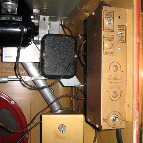
Einbau in spätere
Modelle:
Auf der Rückseite dürfte ganz unten ein ovales, mit einem Drahtgitter
verschlossenes Loch zu finden sein. Für den Einsatz eines Faders
ist dieses Gitter zu entfernen, und der Fader auf dem Boden der Jukebox
innen so zu montieren, dass die Faderbedienelemente (ON-OFF und
Überblendregler) von außen bedienbar sind.
|
|
Installation in later models:
There should be an oval hole at the bottom of the rear panel, closed
with a wire mesh. To use a fader, remove this grille and mount the fader
on the bottom of the jukebox so that the fader controls (ON-OFF and
crossfade control) can be operated from the outside.
|