|
Tastenwahl bei AMI H |
|
Keyboard selection
AMI H |
|
Die Tastatur hat eine
Nullstellung ("home position"), wenn kein Credit registriert ist. In
dieser Stellung dürfen die Tasten nicht einrasten.
Wird Geld eingeworfen wird dies im Kreditwerk registriert und ein
kurzer Impuls läßt den Tastaturmotor ein Stück laufen, die Tasten können
nun einrasten. Werden je eine Taste aus den beiden Tastaturblöcken
gedrückt, wird eine Reihenschaltung (am Ende jedes Tastenblocks ist ein
Kontaktsatz zu finden) komplettiert, die den Motor der Tastatur
loslaufen läßt.
Ist noch ein weiterer Kredit gespeichert, läuft der Tastaturschleifer
bis zur "Creditposition" 360 Grad herum. Hat die getätigte Wahl den
letzten Kredit verbraucht, stoppt der Schleifer so ca. nach 350 Grad in
der oben beschrieben "home position" (Tasten rasten nicht mehr ein). |
|
The keyboard has a zero position ("home position")
when no credit is registered. In this position, the pushbuttons must not
engage.
If money is inserted it gets registered in the credit unit and a short
impulse makes the keyboard motor run a bit, the pushbuttons now can
engage. If one pushbuttons from each of the two keyboard blocks is
pressed, a series connection (there is a set of contacts at the end of
each keyboard block) is completed, which causes the keyboard motor to
run.
If another credit is stored, the keyboard wiper will run 360 degrees
around to the "credit position". If the made selection has subtracted
the last credit, the wiper stops ca. after 350 degrees in the "home
position" described above (pushbuttons no longer engaged). |
|
|
|
Nach
erfolgreicher Wahl läuft das Plattenmagazin nicht an, manuell ausgelöst
funktioniert alles – Modelle AMI G200, H, I |
|
After successful selection the magazin does not
start, but does so when activating manually - models AMI G200, H, I |
|
Offensichtlich wird die Scan-Einheit nicht betätigt. Die Scan-Einheit
sollte bei jeder Wahl betätigt werden und sowohl den Plattenteller-Motor
als auch den Magazinmotor einschalten. Er bleibt so lange eingeschaltet,
bis das Plattenmagazin etwa 1-1/4 Umdrehungen durchgeführt hat.
Die Scan-Einheit ist auf der Rückseite des Popularitätszählers. Wenn Du von hinten unter dem Mechanismus auf den
Popularitätszähler schaust, siehst Du auf der rechten unteren Ecke eine
Spule (hinter dem Blech) und darüber einen Blechwinkel. Die Spule
(eigentlich sind es zwei Spulen nebeneinander) ist der Scan Magnet, der
Blechwinkel ist der Anker, der durch die Spulen betätigt werden soll.
Auf diesem Anker ist ein Rad mit einem halbkreisförmigem,
federbelastetem Segment montiert, das durch die Welle des
Popularitätszählers angetrieben wird.
Für den Antrieb sorgt eine
Gummihülse. Sobald das Plattenmagazin die 1-1/4 Umdrehungen
durchgeführt hat, wird der eigentliche Schalter betätigt. Das ist die
normale Standby-Position. Bei jeder Wahl wird wird das Rad von der
Gummitülle abgehoben und das federbelastete Rad läuft zurück. Dabei wird
der Scan-Schalter freigegeben und die zwei Kontakte (für
Plattentellermotor und Magazinmotor) werden eingeschaltet.
Es kommt vor, dass die Gummitülle eingelaufen ist. Dadurch vergrößert
sich der Abstand zwischen Spule und Anker, und die Kraft des Magneten
reicht nicht mehr aus, um das Rad von der Gummitülle abzuheben. In
diesem Fall kann man versuchen, die Spule (verstellbar) etwas
näher an den Anker zu bringen.
Es kommt auch vor, dass eine tiefe Rille in die Gummitülle eingelaufen
ist. Dann funktioniert das Ganze (evtl. nach Neueinstellung der Spule) im Normalbetrieb wieder.
Dreht man allerdings das Magazin manuell, wird das Rad in die
Rille gezogen und sitzt dort richtig fest. Bei einer anschließenden Wahl
hat der Magnet wieder zu wenig Kraft. Man muss also jedes Mal, wenn man
das Magazin manuell dreht, anschließend einmal den Scanschalter manuell
auslösen (durch drücken auf den Anker), dann funktioniert es wieder. Für
eine dauerhafte Lösung muss die Gummitülle erneuert werden. |
|
Obviously, the scan unit is not activated. The
scan unit should be activated with every selection and switch on both
the turntable motor and the magazine motor. It remains switched on until
the record magazine has completed about 1-1/4 revolutions.
The scan unit is located on the back of the popularity counter. If you
look at the popularity counter from behind below the mechanism, you will
see a coil in the bottom right-hand corner (behind the sheet metal) and
a sheet metal bracket above it. The coil (actually two coils next to
each other) is the scan magnet, the sheet metal bracket is the armature
that is to be actuated by the coils. A wheel with a semi-circular,
spring-loaded segment is mounted on this armature, which is driven by
the shaft of the popularity counter.
The drive is provided by a
rubber sleeve. As soon as the record magazine has completed the
1-1/4 revolutions, the actual switch is actuated. This is the normal
standby position. With each selection, the wheel is lifted off the
rubber sleeve and the spring-loaded wheel runs back. This releases the
scan switch and the two contacts (for the turntable motor and magazine
motor) are switched on.
It can happen that the rubber grommet has worn. This increases the
distance between the coil and the armature, and the force of the magnet
is no longer sufficient to lift the wheel off the rubber sleeve. In this
case, you can try to move the coil (it is adjustable) a little closer to
the armature.
It can also happen that a deep groove has run into the rubber grommet.
Then the whole thing works again in normal operation (possibly after
readjusting the solenoid). However, if the magazine is rotated manually,
the wheel is pulled into the groove and is firmly seated there. If you
then make a selection, the magnet again has too little force. So every
time you turn the magazine manually, you have to trigger the scan switch
manually (by pressing on the anchor), then it works again. But for a
permanent solution, the rubber grommet must be replaced.
|
|
|
|
Nach erfolgreicher Wahl dreht sich das Magazin
nicht – AMI
Continental |
|
After successful selection the magazin does not
rotate – AMI
Continental |
Wenn die Auswahl
korrekt registriert wird, das Schallplattenmagazin sich aber nicht
dreht, arbeitet die Scan Control Unit nicht korrekt. Sie sollte
sowohl den Plattenteller-Motor als auch den Magazinmotor einschalten.
An der Scan Control Unit ist ein Mikroschalter angebracht, der
wahrscheinlich defekt ist.
Wo sitzt der Mikroschalter?
Sie müssen die Abdeckung des Mechanismus entfernen. Dann sehen Sie in
der linken hinteren Ecke, direkt vor dem Schallplattenmagazin, eine
kleine Einheit mit zwei Spulen und dem erwähnten Mikroschalter. Der
Schalter wird im Standby gedrückt. Nach einer Auswahl werden die beiden
Spulen aktiviert und der Schalter fällt ab. Nach etwas mehr als einer
Umdrehung des Magazins wird der Schalter erneut gedrückt. |
|
If the selection is registered correctly, but the record magazine does
not rotate immediately, the scan control unit does not work properly. It
should activate both the turntable and the magazin motors.
The scan control unit has a micro switch which might be faulty.
Where is this micro switch located?
You must remove the mechanism cover. Then you will see on the left rear
corner, right in front of the record magazine, a small unit with two
coils and the mentioned micro switch. The micro switch gets pressed in standby.
After a selection, the two coils are energized and the switch is
released.
After a little more than one turn of the magazine, the micro switch
is pressed again. |
|
|
|
Nach erfolgreicher Wahl wird die Single aufgelegt und sofort wieder zurück ins Magazin
gestellt - Modell K, Lyric und Continental |
|
After successful selection the record gets
placed on the turntable and immediately returned - models K, Lyric and
Continentals |
Die Wahl des Titels funktioniert einwandfrei. Die Single
wird aus dem richtigen Fach gezogen und dann aufgelegt, aber dann leider
gleich wieder zurückgelegt.
Der Cut-Off-Switch und der Camshaft-Switch sind überprüft und in
Ordnung. Ebenso verhält es sich mit den Einstellungen der übrigen
Camshaft Switche.
Das Reverse Relais zieht mit dem Zurücksetzen des Wahlpins an und fällt
erst beim Zurücklegen der Platte wieder ab. Wenn ich die Netzspannung
beim Erreichen des Aufsetzpunktes der Nadel auf die Platte kurz
unterbreche, fällt das Reverse Relais ab und alles funktioniert wie es
soll.Antwort: Manche Continentals (und
ähnliche) machen diesen
Fehler, wenn das Mute Relais im Basic-Verstärker (R-2017, R-2777) nicht
angeschlossen ist. |
|
The selection of the song works fine. The record
is taken out of the right slot and placed on the turntable, but then
unfortunately immediately returned.
The cut-off switch and the camshaft switch are checked and fine. The
same applies to the adjustments of the other camshaft switches.
The reverse relay attracts as the select pin is reset and does not
release until the record is returned.
If I briefly interrupt the mains voltage when the needle reaches the
record, the reverse relay releases and everything works as it should.
Answer: Some Continentals (and models a
like) make this error if the muting relay in the basic amplifier
(R-2017, R-2777) is not connected. |
|
|
|
Ablauf nach
getätigter Wahl - ROWE/AMI ab JAL, JBM etc. |
|
Sequence after making a selection - ROWE/AMI
from JAL, JBM etc. |
|
Wenn eine Buchstaben- und eine Zifferntaste
gedrückt werden, läuft der Search Unit-Motor an. Sobald der vordere
Schleifkontakt auf das entsprechende Ziffernsegment kommt, zieht das
rechte Sprag Relay (das mit dem Hebel, der in das Zahnrad eingreift) an.
Das Zahnrad (Sprag Wheel) hat eine flach verlaufende Kurve und eine
etwas tiefere Kerbe. Die Kontakte auf dem Sprag Relay dürfen erst
schalten, wenn der Hebel in die tiefe Kerbe fällt. Einer der Kontakte
schaltet den Motor aus, der zweite aktiviert das Search Unit Relay. Das
Search Unit Relay hält sich über einen Selbsthaltekontakt selbst bis zum
Ende des Wahlvorgangs. Es deaktiviert nun das rechte Sprag Relay und
bereitet den Stromkreis für das linke Sprag Relay vor. Dadurch fällt das
rechte Sprag Relay wieder ab und der Motor beginnt wieder zu laufen.
Sobald der hintere Schleifkontakt auf das entsprechende
Buchstabensegment kommt, zieht das linke Sprag Relay an. Wenn der Hebel
in die Kerbe fällt, werden die Konakte geschlossen, wobei einer davon
das Select Coil aktiviert, um den Wahlpin zu schlagen. Auch hier dürfen
die Kontakte erst schalten, wenn der Hebel in die Kerbe fällt. |
|
When a letter key and a number key got pressed,
the search unit motor starts. As soon as the front wiper contact comes
onto the corresponding number segment, the right sprag relay (the one
with the lever that engages the gear wheel) attracts.
The gear (sprag wheel) has a flat curve and a slightly deeper notch. The
contacts on the sprag relay may not switch until the lever falls into
the deep notch. One of the contacts turns the motor off, the second one
activates the search unit relay. The search unit relay holds itself
until the end of the selection sequence via a latching contact. It now
deactivates the right sprag relay and prepares the circuit for the left
sprag relay. This causes the right sprag relay to release again and the
motor to start running again. As soon as the rear wiper contact comes
onto the corresponding letter segment, the left sprag relay pulls in.
When the lever drops into the notch, the contacts are closed, one of
which activates the select coil to strike the selection pin. Again, the
contacts may not switch until the lever drops into the notch. |
|
|
|
Plattenmagazin
stoppt mehrere Wahlen zu spät, währenddessen schließt sich bereits der
Greifer - ROWE/AMI ab JAL, JBM etc. |
|
Record magazine stops several selections too
late, while the gripper is already closing - ROWE/AMI from JAL, JBM
etc. |
|
Solange das Magazin läuft, ist das Magazin Detent Solenoid angezogen.
Das ist die Spule ganz unten auf dem Magazinmotor (Sprag Assembly
genannt). Der Motor selbst wird über den Magazin Detent Switch (und
Camshaft Switch Nr. 1 - CS1) eingeschaltet. Der Detent Switch ist nicht betätigt
(Motor ist eingeschaltet), solange die Spule angezogen ist. Der CS1
öffnet den Stromkreis, sobald der Transfer Motor anläuft und der Greifer
geschlossen wird.
Wenn der Stop Switch betätigt wird (weil ein gesetzter Wahlpin gefunden
wurde), zieht das Mechanism Control Relay an. Dadurch fällt das Magazin
Detent Solenoid ab. Der Hebel darauf bewegt sich zum Sprag Wheel. Wenn
die nächste Kerbe vorbeikommt, wird der Hebel mitgenommen und rastet
ein. Dabei wird der Magazin Detent Switch betätigt und dieser schaltet
den Magazin Motor aus. Das Mechanism Control Relay schaltet gleichzeitig auch den
Transfer Motor ein. Sobald dieser zu drehen beginnt, öffnet der CS1 und
unterbricht zusätzlich den Strom zum Magazin Motor.
Das Control Relay schaltet also gleichzeitig das Detent Solenoid aus und
den Transfer Motor ein. Der Magazin Motor läuft noch so lange weiter,
bis der Hebel eingerastet ist. Hier dürfte der Fehler in Deinem Fall zu
suchen sein. Wenn der Plunger des Solenoids klebrig ist, kann es
passieren, dass der Hebel nur langsam auf das Sprag Wheel fällt und erst
einige Plattenpositionen später einrastet. Der Magazin Motor wird erst
abgeschaltet, wenn das passiert ist oder spätestens dann, wenn der CS1
öffnet.
Der Plunger sollte ausgebaut und entfettet werden, ebenso die Hülse im
Solenoid. Beides muß absolut fettfrei sein. Außerdem sollte der
Mikroschalter durchgemessen und die mechanische Funktion geprüft werden.
Es sollte auch kontrolliert werden, ob der Hebel richtig im Sprag Wheel
einrastet. Manchmal ist der Hebel etwas verbogen und rastet schlecht
ein.
|
|
As long as the magazine is scaning, the magazine
detent solenoid is attracted. This is the solenoid at the bottom of the
magazine motor (called the sprag assembly). The motor itself is switched
on via the magazine detent switch (and camshaft switch no. 1 - CS1). The
detent switch is not actuated (motor is switched on) as long as the
solenoid is attracted. The CS1 opens the circuit as soon as the transfer
motor starts and the gripper is closed.
When the stop switch is actuated (because a set selector pin has been
found), the mechanism control relay is energized. This causes the
magazine detent solenoid to release. The lever on it moves to the sprag
wheel. When the next notch passes, the lever is pulled along and engages.
This actuates the magazine detent switch, which switches off the
magazine motor. The mechanism control relay also switches the transfer
motor on at the same time. As soon as this starts to rotate, the CS1
opens and also interrupts the current to the magazine motor.
The control relay therefore switches the detent solenoid off and the
transfer motor on at the same time. The magazine motor continues to run
until the lever is engaged. This is probably the fault in your case. If
the plunger of the solenoid is sticky, it can happen that the lever only
falls slowly onto the sprag wheel and only engages a few record
positions later. The magazine motor is only switched off when this
happens or at the latest when the CS1 opens.
The plunger should be removed and degreased, as should the sleeve in the
solenoid. Both must be absolutely free of grease. In addition, the micro
switch should be measured and the mechanical function checked. It should
also be checked whether the lever engages correctly in the sprag wheel.
Sometimes the lever is slightly bent and engages poorly. |
|
|
|
ROWE/AMI spielt die Wahlen des
6er Blocks nicht |
|
Rowe/AMI does not play selections of the
6-block |
|
Alle Wahlen beginnend mit einer "6"
werden nicht genommen. Der Suchermotor läuft an, das linke Sprag Relay
zieht an, aber der Hebel fällt nicht weit genug in die Kerbe.
Antwort: vermutlich liegt dies an der Einstellung des vorderen
Schleifkontaktes. Dieser ist relativ leicht einzustellen.
Man geht folgendermaßen vor:
1. anwählen einer Single der Gruppe "0", z. B. A0.
Damit steht der Schleifkontakt unmittelbar vor dem Segment "1". Dieses
Segment ist mit einer Markierung versehen.
2. Nun die Search Unit, bzw. den Arm mit den Select Coils (vor dem
Stiftrad) GEGEN DEN UHRZEIGERSINN händisch weiterdrehen und dabei den
Arm des rechten Sprag Relay niederdrücken. Nach etwa einer Umdrehung des
Nockenrades rastet der Hebel des Sprag Relay in die tiefe Kerbe ein.
3. Der Schleifkontakt muss nun genau neben der Markierung auf dem
Segment "1" stehen. Vermutlich steht der Kontakt etwas weiter vorn oder
weiter hinten.
4. Zum Einstellen wird die Inbusschraube gelockert und der
Schleifkontakt genau auf die Markierung gestellt, wobei der Hebel des
Sprag Relay immer noch in die Kerbe gedrückt ist.
Achtung: zum händischen Weiterdrehen
immer mit den Select Coil-Armen GEGEN DEN UHRZEIGERSINN,
niemals mit dem Schleifkontakt drehen (im Uhrzeigersinn). Die
Schleifkontakte könnten dabei beschädigt werden. |
|
All selections beginning with a "6" are not taken.
The search motor starts, the left sprag relay attract, but the
lever does not fall deep enough into the notch.
Answer: This is probably due to the setting of the front sliding contact.
This is relatively easy to adjust.
Proceed as follows:
1. Select a record from group "0", e.g. A0.
This places the sliding contact directly in front of segment "1". This
segment is marked.
2. Now continue turning the search unit or the arm with the select coils
(in front of the pin wheel) COUNTERCLOCKWISE by hand while pressing down
the arm of the right-hand sprag relay. After about one rotation of the
cam wheel, the lever of the sprag relay engages in the deep notch.
3. The sliding contact should now be exactly next to the marking on
segment "1". The contact is probably a little further forward or further
back.
4. To adjust, loosen the Allen screw and place the sliding contact
exactly on the marking, with the lever of the sprag relay still pressed
into the notch.
Caution: To continue turning manually, always turn with the
select coil
arms COUNTERCLOCKWISE. Never turn with the sliding contact (clockwise).
This could damage the sliding contacts.
|
|
|
Statt A-Seiten werden nur B-Seiten gespielt
ROWE/AMI JAL, JEL u.a. bis in die 1970er |
|
Instead of A- only B-sides get played
ROWE/AMI JAL, JEL et al. up
to the 1970s |
|
Eine ROWE/AMI der 1970er Jahre nimmt alle
Wahlen an, die Wahlstifte werden richtig geschossen. Es werden aber nur B-Seiten
gespielt. Wird eine A-Seite gedrückt, funktionieren
die Seitenumschalt- und die Löschspule dafür nicht.
Bei "Seite-B-Wahlen" funktioniert alles, auch die Löschspule für
B-Stifte. Was kann die Ursache sein?
Antwort:
Wahrscheinlich ist der Mikroschalter für die Abfragung der A-Seiten
defekt. Er befindet sich auf der "Stopping Switch, Gear And Reset
Solenoid Assembly". Das ist die Einheit hinter dem Stiftrad. Darauf gibt
es zwei Mikroschalter: einer ist zuständig für das Stoppen des Magazins.
Er wird sowohl bei A- als auch bei B-Seiten betätigt und scheint
in Ordnung zu sein. Der zweite wird nur bei A-Seiten betätigt. Er
schaltet die Reset Solenoids um und betätigt das Toggle Shifter Solenoid
(neben dem Greifer). Der Mikroschalter ist neben dem längeren Sucherarm
für die äußere Stiftreihe montiert.
Zugang zu dem Schalter bekommt man, wenn man die Search Unit abmontiert.
Sie ist mit drei Sechskantschrauben befestigt und benötigt keinerlei
Einstellarbeiten beim Montieren. Die Stopping Switch-Einheit könnte man
ebenfalls leicht abmontieren, sie ist nur mit einem großen E-Ring auf
der Mittelachse befestigt. Allerdings muss beim Einbau auf die richtige
Stellung geachtet werden. Wenn das Magazin auf der Platte A1 steht, muss
die "200" - Markierung genau mit der Kante auf dem Blech daneben
übereinstimmen.
Der Mikroschalter sollte ausgebaut,
gemessen, ggfs. auseinandergebaut, gereinigt und neu justiert werden. Das
erweist sich leider als recht kniffelig. |
|
A ROWE/AMI from the 1970s accepts all selections, the selector pins are shot correctly.
However, only B-sides get played. If an A-side is pressed,
the changeover and the cancel coil for A-sides do not work.
With "side B selections" everything works, including the cancel coil for B
selection pins. What could be the cause?
Answer: The microswitch for scanning the A sides is probably defective.
It is located on the "Stopping Switch, Gear And Reset Solenoid Assembly". This
is the unit behind the pin wheel. There are two microswitches on it: One is
responsible for stopping the magazine. It is actuated for both A-sides and
B-sides and seems to be in order. The second is only actuated for A-sides. It
switches the reset solenoids and operates the toggle shifter solenoid (next to
the gripper). The microswitch is mounted next to the longer viewfinder arm for
the outer row of pins.
Access to the switch is gained by removing the search unit. It is attached with
three hexagon head screws and does not require any adjustment when mounting. The
stopping switch unit can also be easily removed, it is only attached to the
center axle with a large E-ring. However, the correct position must be ensured
during installation. When the magazine is on the A1 reord , the "200" mark must
correspond exactly with the edge on the record next to it.
The microswitch should be removed, measured, disassembled if necessary, cleaned
and readjusted. Unfortunately, this proves to be quite tricky. |
|
|
|
Der Pin
Pusher betätigt die Pins nicht weit genug -
AMI G, H, I, J, K, Lyric- und Continental Modelle |
|
Pin Pusher doesn't push the pins far enough -
AMI G, H, I, J, K, Lyric-
and Continental models |
|
Der Stiftschläger (Pin Pusher) ist sehr lasch und stösst den Pin nur die
Hälfte rein. Selektor und Wahlrad sind ok, die Selektorstifte sind
leichtgängig, die Solenoidspule ist ebenfalls in Ordnung.
Wenn ich eine externe Spannung von ca. 20 Volt anlege, wird der Pin
kraftvoll eingedrückt. Netzteil und alle Kontakte wurden repariert bzw.
gereinigt. Was kommt hier noch in Frage?
Antwort:
Die Stiftschläger sollen einen Abstand von 2 - 3 mm zu den Pins haben.
Justierung Pin-Pusher.
Es kann sinnvoll sein, den Gleichrichter zu prüfen.
Der Einschreibimpuls für die Spule kommt über das Relais / Spule
oben rechts am Selektor. Dort gibt es noch mindestens einen Elko und ein
oder zwei Folienkondensatoren. Leider sind die Entstörkondensatoren
nicht in den Plänen eingezeichnet. Meistens fehlen die auch schon, sie
machen heute häufiger Probleme. Wenn der noch eingebaut ist - an dem
Lötanschluss-Terminal oben rechts hinter/unter dem Scanschalter - dann
könnte der einen Schluss machen und so die Spannung herunter ziehen.
Darüberhinaus müssen alle beteiligten Kontakte natürlich richtig
justiert sein. |
|
The pin pusher is very weak and pushes the pin
only halfway in. The selector and selector wheel are ok, the selector
pins are smooth, the solenoid coil is also ok.
When I apply an external voltage of about 20 volts, the pin is
forcefully pushed in. Power supply and all contacts have been repaired
or cleaned. What else can be considered here?
Answer: The pin pushers should have a distance of 2 - 3 mm to the
pins. Adjustment Pin-Pusher.
It may be useful to check the rectifier.
The write-in pulse for the coil comes from the relay/coil at the top
right of the selector. At least there is one more electrolytic capacitor
and one or two film capacitors. Unfortunately the suppression capacitors
are not drawn in the schematics. Mostly they are already missing, they
cause problems more often nowadays. If the one is still installed - at
the solder terminal on the top right behind/below the scan switch - then
it could make a short and so pull down the voltage.
In addition, all contacts involved must of course be properly adjusted. |
|
|
|
Der Pin
Pusher betätigt die Pins nicht weit genug -
ROWE/AMI der 70er |
|
Pin Pusher doesn't push the pins far enough -
Rowe/AMI 1970s |
|
Der Pin Pusher einer ROWE/AMI der 1970er
stoppt vor dem richtigen Pin. A1 auf dem Selector ist markiert, jedoch
tippt er die Pins nur leicht an und schlägt sie nicht weit genug ein, so
dass der Pin nicht erkannt wird. Alle Pins sind leichtgängig. Was könnte
die Ursache sein?
Antwort:
Ist die Spule, die sich im Inneren der Magazinachse befindet, richtig
befestigt? Die Spule hat eine Kerbe, in die das Metallplättchen auf dem
Stiftrad eingreifen muß.
Die Pinpusher sollen einen Abstand von 2 - 3 mm zu den Pins haben.
Justierung Pin-Pusher.
Wenn die Spule richtig befestigt ist und der Abstand nicht zu groß ist,
kommt noch ein Kontaktproblem im Selector in Frage. Der verantwortliche
Kontakt ist auf dem Stoprelais (das mit dem langen Hebel, der in das
Zahnrad eingreift). Die Kontakte müssen gereinigt und justiert werden. |
|
The pin pusher on a 1970s ROWE/AMI stops at the
correct pin. A1 on the selector is marked, but it only taps the pins
slightly and does not push them far enough, so the pin is not recognized.
All pins are free and move easily. What could be the cause?
Answer: Is the coil, which is located inside the magazine shaft,
properly attached? The coil has a notch where the metal plate on the
pinwheel must engage.
The pin pushers should have a distance of 2 - 3 mm to the pins. Compare
Adjustment Pin-Pusher.
If the coil is properly mounted and the distance is not too long, a
contact problem in the selector might be the problem. The contact
responsible is at the stop relay (the one with the long lever that
engages the gear). The contacts must be cleaned and adjusted |
|
|
|
Gleiche Wahl wird ständig wiederholt - Modelle
1970er Jahre: |
|
Same selections gets played again and again -
models 19770s: |
|
Meine Rowe/AMI CDII (1971) wiederholt die
gleiche Wahl immer wieder, obwohl verschiedene Nummern gewählt wurden.
Dann plötzlich geht es wieder und die nächste Wahl wird getätigt. Der
Fehler tritt also nicht immer auf.
Antwort:
Für den Fehler an der CMM4/CDII kommen verschiedene Ursachen in Frage.
Als erstes sollte festgestellt werden, ob der Pin auf der Wahleinheit (Search
Unit) zurückgesetzt wird, wenn die Platte zu spielen beginnt. Wenn der
Pin nicht zurückgesetzt wird, liegt es meistens an einem defekten
Mikroschalter auf der Suchereinheit (Stop Switch Unit). In diesem Fall
wird meistens die "B" - Seite der Platte gespielt, obwohl die "A" -
Seite gewählt wurde.
Wenn der Pin zurückgesetzt wurde und die gleiche Platte trotzdem wieder
aufgelegt wird, dürfte der Fehler an dem Nockenschalter (Cam Switch)
liegen, der den Transfermotor (bzw. das Mechanism Control Relay)
ausschaltet, wenn die Platte in das Magazin zurückgelegt ist. |
|
My Rowe/AMI CDII (1971) keeps repeating the same
selection even though different numbers have been selected. Then
suddenly it works again and the next selection gets played. So the error
does not always occur.
Answer:
There are several possible causes for the error on the CMM4/CDII. The
first thing to do is to determine whether the pin on the search unit
gets reset as soon as the record starts playing. If the pin does not get
reset, it is usually due to a defective microswitch on the search unit (stop
switch unit).
In this case, the "B" side of the record gets usually played even though
the "A" side was selected.
If the pin has been reset and the same record is still put back on, the
fault is likely to be looked for in the cam switch that switches off the
transfer motor (or the mechanism control relay) when the record is put
back into the magazine.
|
|
|
|
Rowe/AMI
TI-1 schreibt Wahlen von "N" bis "S" nicht ein. |
|
Rowe/AMI TI-1 doesn't write in selections from
"N" to "S" |
|
Problem: Das Sprag Relay zieht einmal kurz an, jedoch
wird kein Stift gesetzt, und danach drehen die Schleifkontakte endlos
weiter. Die Schleifer wurden bereits auf die 1-Markierung ausgerichtet,
jedoch ohne weiteren Erfolg.
Antwort:
Da die "S"-Wahlen nicht funktionieren, die "T"-Wahlen aber
doch, dürfte der Fehler in der Tastatur zu suchen sein. Die beiden
Gruppen aktivieren nämlich das gleiche Kontaktsegment auf der Search
Unit. Die Sprag Relais werden an der gleichen Position
aktiviert, es wird nur die Select Coil (innerere oder äußerere Pin-Reihe) umgeschaltet.
Die Tastaturkontakte N bis S sollten mit dem Ohmmeter überprüft werden. Zuständig ist die erste Kontaktreihe, die Stromzuführung ist die Leitung
ganz rechts an der V-Taste. Von dort muss auf die entsprechenden
abgehenden Leitungen (insgesamt 10, eine Leitung für je 2 Tasten)
durchgeschaltet werden. |
|
Problem: The sprag relay attracts once
shortly, however no pin is set, and then the wipers continue to rotate
endlessly. The wipers have already been aligned to the marking "1" but
without further success.
Answer:
Since the "S" selections do not work, but the "T" selections do, the
error is probably located in the keyboard.
Those two groups activate the same contact segment on the search unit.
The sprag relays are activated at the same position and only the select
coil (inner or outer pin row) gets switched.
The keyboard contacts N to S should be checked with the ohmmeter.
Responsible is the first row of contacts, the current supply is the wire
on the right side of the pushbutton "V". From there it should be
connected to the corresponding output lines (10 in total, one line for
each 2 buttons). |
|
|
|
Rowe/AMI
TI-2 nimmt Kredit, die Tasten rasten ein, der
Suchvorgang startet, aber es wird keine Wahl gefunden. |
|
Rowe/AMI Ti-2 accepts credit, pushbuttons lock
down, searching starts but no selections get found |
- Stop Switch ohne Durchgang:
prüfen der Leitungen zum Stop Switch
-
Gewählter Stift nicht
weit genug gesetzt:
überprüfen der inneren und äußeren Reihen der Wahlspulen auf
korrektes Arbeiten
-
Wahlspule nicht
richtig positioniert: Arm mit Wahlspulen richtig einstellen
-
Stop Switch ohne
Durchgang:
überprüfen des Stop Switches
und Schleifer auf der Rückseite des Stop Switches
-
Diode D2 defekt:
prüfen und ggfs. ersetzen
-
Kurzschluss im 50 µF
Kondensator:
prüfen und ggfs. ersetzen
-
Fehlerhaftes
Mechanismusrelais: prüfen und
ggfs. ersetzen
-
CS5 Nockenschalter
defekt or falsch justiert: Nockenschalter auf richtige Funktion
prüfen, ggfs. ersetzen und justieren
-
Kurzschluss
Magazin-Rastspule: prüfen uns ggfs. ersetzen
|
|
-
No circuit through stop switch: Check wiring of stop switch
-
Selected pin not pushed far enough:
Check inside and outside row select coils for proper operation
-
Select coil not properly positioned:
Adjust the arm with selection coils properly
-
No circuit through step switch:
Check stop switch and wipers on back of stop switch
-
Diode D2 defective: Check/replace
-
Short circuit in 50 µF capacitor:
Check/replace
-
Faulty mechanism relay: Replace
-
CS5 cam switch defective or out of
adjustment: Check/replace cam switch for proper operation, adjust
switch position
-
Short circuit on common side of
magazine detent coil: Check/replace
|
|
|
Rowe/AMI
JAL greift die Singles um ein Fach versetzt heraus
auch folgende Modelle |
|
Rowe/AMI JAL always takes the record offset by
one slot
also later models |
|
Prüfen, ob die Einstellung des Mechanismus korrekt ist.
Prüfen, ob die Markierung 200 (oder 00) auf der Anschlagplatte gegenüber
der Stufe in der Halterung des Such-Einheit (rechts) gemäß dem Handbuch
richtig eingestellt ist, indem der Wartungsschalter auf die Position A1
gestellt wird.
Wenn diese Einstellung korrekt ist, prüfen, ob der Such-Einheit richtig
eingestellt ist und den richtigen Stift herausdrückt.
Zum Testen der Such-Einheit die folgenden Titel wählen:.
A1, C2, E3, G4, J5, L6, N7, Q8, S9 und U0.
Dann die B-Seiten testen. |
|
Check that the timing of the mechanism is correct.
To do so, by using the service switch scan around to the A1
position.
Now check that the 200 (or 00) mark on the stop plate opposite the step
in the search unit bracket (right) is set correctly according to the
service manual by setting the service switch to position A1.
If this adjustment is correct, check that the search unit is adjusted
correctly and pushes out the correct pin.
I usually test a search unit by selecting the following numbers:
A1, C2, E3, G4, J5, L6, N7,Q8,S9 and U0. Then the B
sides should be tested. |
|
|
|
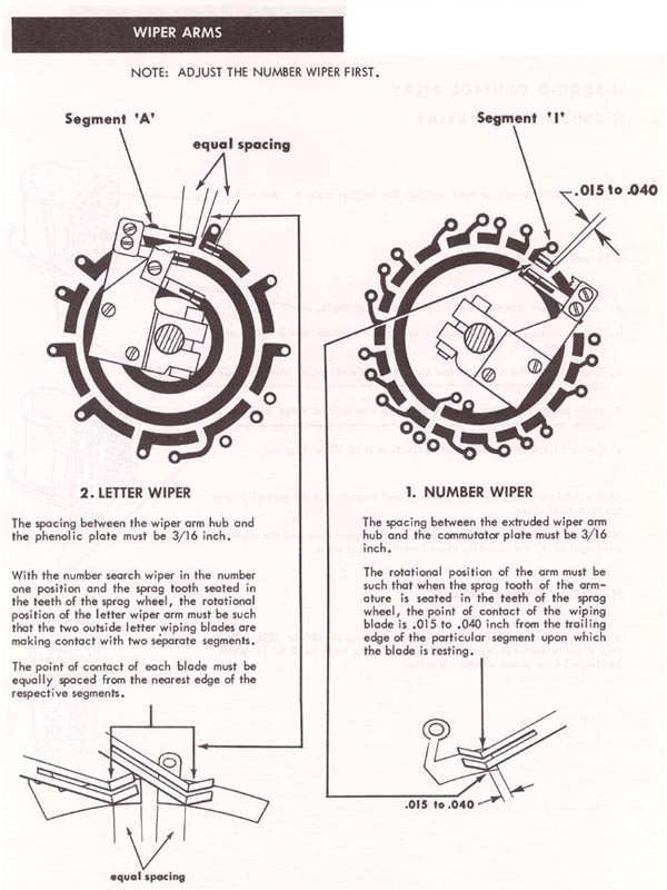
Kontaktschleifer – Einstellung - Modelle K (späte Serie) bis Continental 2 |
|
Wiper
arms: Adjustment - models K (late series) to Continental 2 |
Einbau und Justierung der
Kontaktschleifer bei den späten K- Modellen sowie Continental und Continental
2. Diese Musikboxen haben - im Gegensatz zu den Vorgängermodellen - keinen
eingebauten Stepper (Pulse Generator und Receiver), sondern die Tasten
sind direkt mit der "Wähleinheit" für Buchstaben und Zahlen verbunden. |
|
Installation
and adjustment of wiper arms on late series AMI K, Continental
and Continental 2. These jukeboxes have - compared to
predecessor models - no installed stepper (pulse generator and
receiver) but pushbuttons which are connected directly with the
selection unit for letters and numbers.
|
 |
|
Die Angaben haben keinen
Anspruch auf Vollständigkeit oder Richtigkeit.
Bei den (importierten) Boxen können im Laufe der Jahre durchaus
Veränderungen vorgenommen worden sein. Copyright.
<<<
zur
Archiv Startseite
|
|
Ein Service von

Copyright by
Stamann Musikboxen |